


-
摘要:
对于采用下单翼布局翼吊发动机形式的大型客机而言,为了保证发动机与地面的安全距离,挂架高度较短,造成前缘缝翼被打断,大迎角下发动机短舱尾迹对其后方机翼上翼面的流动产生不利影响。采用数值模拟方法系统研究了在发动机挂架后方机翼上表面采用主动流动控制技术来提高着陆构型的气动性能。采用机翼+短舱构型研究了吹气参数对吹气效果的影响。结果表明:大迎角下,吹气可以抑制短舱后方机翼上表面的分离流动,使最大升力系数明显提高;吹气缝宽度、吹气质量流率由于会影响吹气总压的变化,对吹气效果的影响显著,对升力系数的影响量在0.05以上;吹气缝与上翼面夹角会影响能量注入的区域,对吹气效果有较大影响;吹气缝位置会影响吹气控制的范围,对吹气效果也有一定影响。分别对无短舱涡流片和有短舱涡流片的全机构型进行了校核研究。采用吹气措施之后,无短舱涡流片构型线性段升力系数增大约0.15,最大升力系数增大0.186,失速迎角增大1°;有短舱涡流片构型线性段升力系数增大约0.13,最大升力系数增大0.16。
Abstract:For airliner with a wing-mounted engine layout, in order to ensure ground clearance, the pylon has to be short, which leads to a slat cutout, and the nacelle wake of the engine generates low energy flow and even flow separation on the upper wing surface. Numerical simulation method has been used to systematically study active flow control technology at wing-engine junction of airliner to improve the aerodynamic performance of the landing configuration. The influence of the blowing parameters on blowing performance was studied using the wing-nacelle configuration. The results show that, at high angles of attack, blowing can suppress the separation of the upper surface of the wing behind the nacelle, and the maximum lift coefficient can be significantly improved. Since the width of the blowing slot and the blowing mass flow rate influence the total pressure of blowing air, they show great effects on the blowing performance with the improvement of the lift coefficient of more than 0.05. The angle between the blowing slot and the upper wing surface affects the area of blowing energy, making a considerable effect on the blowing performance. The position of blowing slot affects the control range of the blowing air, which also has some effects on the blowing performance. Finally, the full-body configuration with and without nacelle vortex fins were studied respectively. For the configuration without nacelle vortex fin, the lift coefficient of the linear segment increases by about 0.15, the maximum lift coefficient increases by 0.186, and stall angle of attack increases by 1°. For the configuration with nacelle vortex fin, the lift coefficient of the linear segment increases by about 0.13, and the maximum lift coefficient increases by 0.16.
-
Key words:
- flow control /
- flow separation /
- lift coefficient /
- slat /
- landing configuration /
- large bypass ratio
-

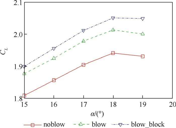
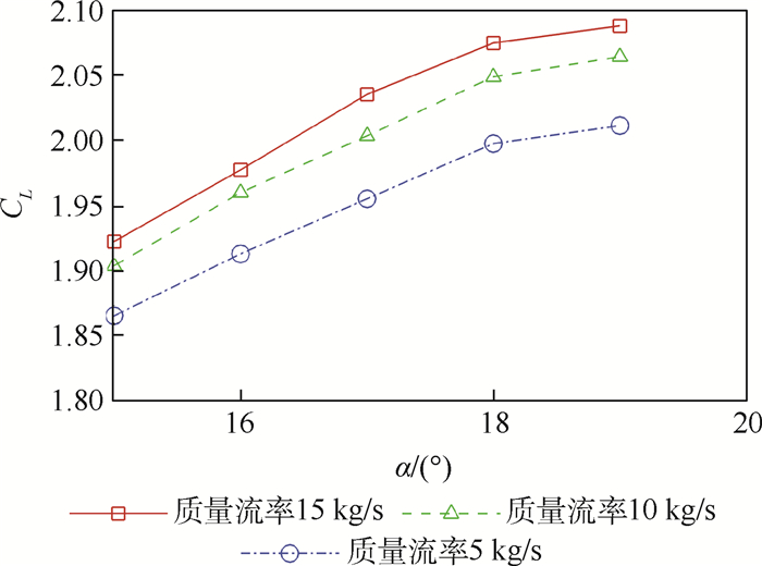
图 8 noblow、blow和blow_block升力特性对比
Figure 8. Lift coefficient comparison of noblow, blow and blow_block

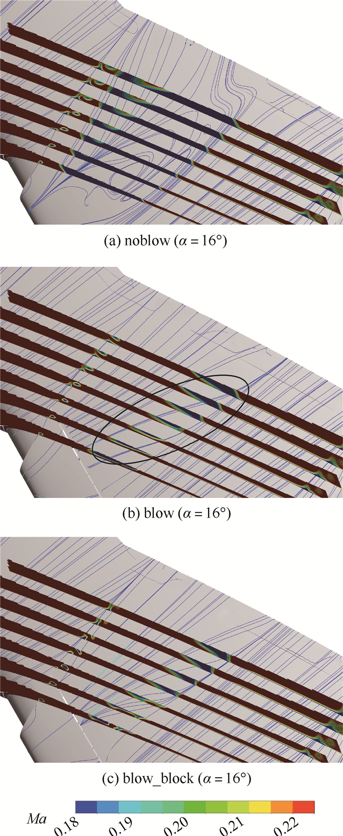
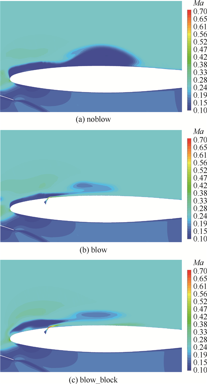
图 9 机翼上表面流线和边界层附近马赫数云图
Figure 9. Streamline on upper surface of wing and Mach number contour around boundary layer

图 12 不同堵块数量升力特性对比
Figure 12. Lift coefficient comparison of different number of blocks

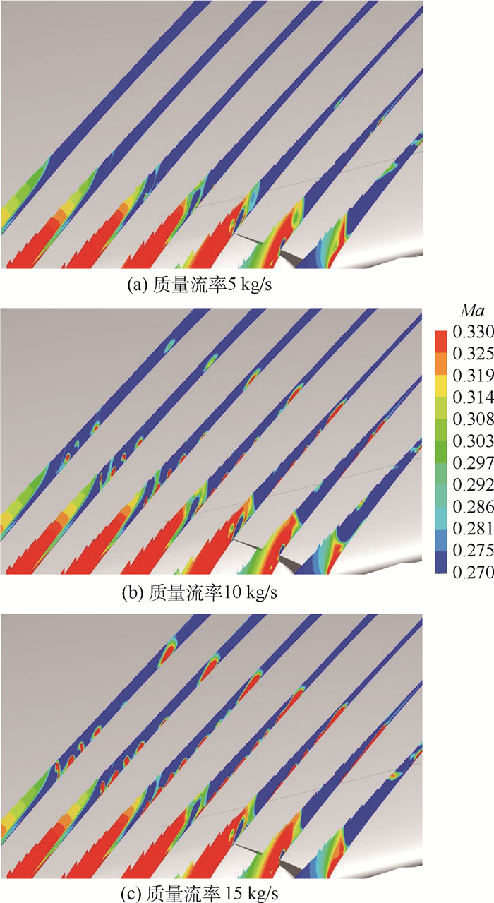
图 13 短舱后方机翼上表面剖面马赫数云图
Figure 13. Mach number contour on upper-sectional surface of wing behind nacelle

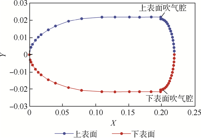
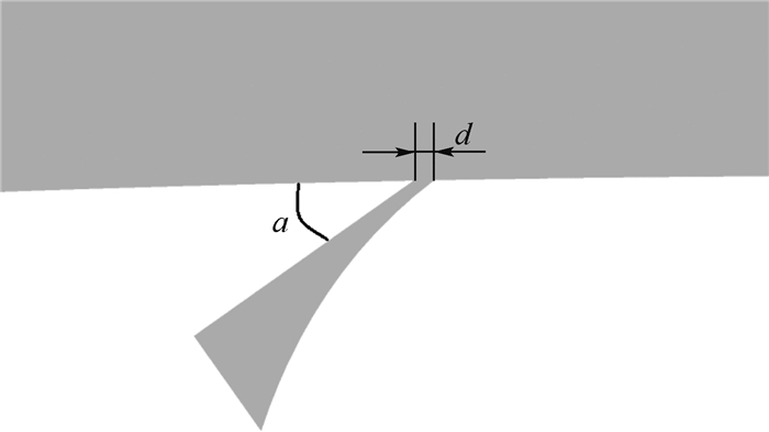
图 14 吹气缝宽度及与吹气缝和上翼面夹角定义
Figure 14. Definition of the width of blowing slot and the angle between blowing slot and upper surface of wing

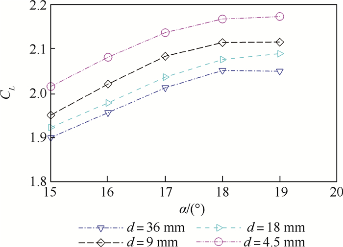
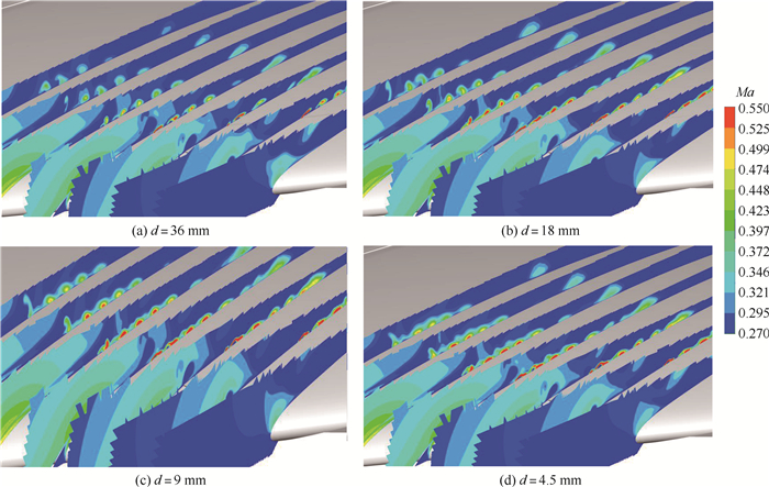
图 16 不同吹气缝宽度短舱后方机翼上表面剖面马赫数云图
Figure 16. Sectional Mach number contour on upper surface of wing behind nacelle of different slot width

图 17 不同吹气缝与上翼面夹角升力特性对比
Figure 17. Lift coefficient comparison of different angles between blowing slot and upper wing surface

图 18 不同吹气缝与上翼面夹角机翼上表面剖面马赫数云图
Figure 18. Mach number contour on the sectional surface of upper wing of different angles between blowing slot and upper wing surface

图 20 短舱后方机翼上表面剖面马赫数云图
Figure 20. Mach number contour on upper-sectional surface of wing behind nacelle

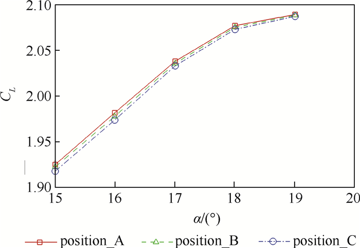
图 22 不同吹气缝位置升力特性对比
Figure 22. Lift coefficient comparison of different blowing slot positions

图 23 不同吹气缝位置机翼上表面剖面马赫数云图
Figure 23. Mach number contour on the sectional surface of upper wing of different blowing slot positions

图 24 noblow_nochine和blow_nochine升力特性对比
Figure 24. Lift coefficient comparison of noblow_nochine and blow_nochine

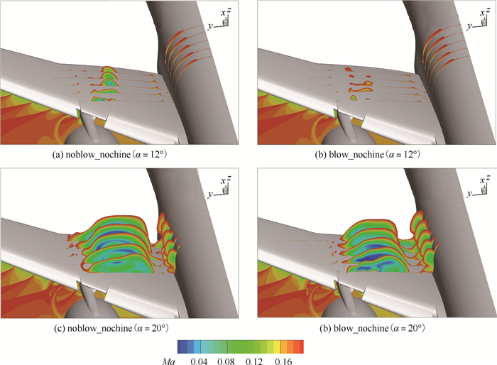
图 25 noblow_nochine和blow_nochine机翼上表面多剖面马赫数云图
Figure 25. Mach number contour comparison of noblow_nochine and blow_nochine on the sectional surface of upper wing

图 26 noblow_nochine和blow_nochine机翼剖面马赫数云图对比
Figure 26. Mach number contour comparison of noblow_nochine and blow_nochine at wing section

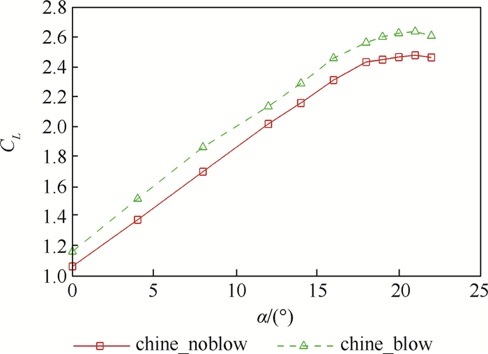
图 28 chine_noblow和chine_blow升力特性对比
Figure 28. Lift coefficient comparison of chine_noblow and chine_blow

图 29 chine_noblow和chine_blow机翼上表面剖面马赫数云图对比
Figure 29. Mach number contour comparison of chine_noblow and chine_blow on the sectional surface of upper wing

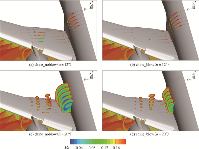
图 30 chine_noblow和chine_blow机翼剖面马赫数云图对比
Figure 30. Mach number contour comparison of chine_noblow and chine_blow at wing section
表 1 不同网格量气动力系数对比
Table 1. Comparison of aerodynamic coefficients
网格量/104 升力系数CL 阻力系数CD 14.5 2. 770 0.0 495 26.8 2. 796 0.0 491 53.6 2. 818 0.0 488  下载: 导出CSV
-
[1] 王志栋. 翼吊发动机对机翼设计的影响分析[J]. 民用飞机设计与研究, 1997(2): 19-22. https://www.cnki.com.cn/Article/CJFDTOTAL-MYFJ199702003.htmWANG Z D. Analysis about influence of wing-mounted engine nacelle on wing design[J]. Civil Aircraft Design and Research, 1997(2): 19-22(in Chinese). https://www.cnki.com.cn/Article/CJFDTOTAL-MYFJ199702003.htm [2] BABIĆ R Š, TATALOVIĆ M, BAJIĆ J. Air transport competition challenges[J]. International Journal for Traffic and Transport Engineering (IJTTE), 2017, 7(2): 144-163. [3] JOHN A. Improving jet engine aerodynamic design via novel component shaping and analysis[D]. Sheffield: University of Sheffield, 2018. [4] LANGE F B. Aerodynamic optimization of an UHBR engine position on a representative short range aircraft configuration at cruise flight conditions[C]//2018 Applied Aerodynamics Conference. Reston: AIAA, 2018: 3811. [5] SCHLOESSER P, SOUDAKOV V, BAUER M, et al. Active separation control at the pylon-wing junction of a real-scale model[J]. AIAA Journal, 2019, 57(1): 132-141. doi: 10.2514/1.J057345 [6] 邱亚松, 白俊强, 黄琳, 等. 翼吊发动机短舱对三维增升装置的影响及改善措施研究[J]. 空气动力学学报, 2012, 30(1): 7-13. doi: 10.3969/j.issn.0258-1825.2012.01.002QIU Y S, BAI J Q, HUANG L, et al. Study about influence of wing-mounted engine nacelle on high-lift system and improvement measures[J]. Acta Aerodynamica Sinica, 2012, 30(1): 7-13(in Chinese). doi: 10.3969/j.issn.0258-1825.2012.01.002 [7] 白俊强, 刘南, 邱亚松, 等. 民用运输机短舱涡流片设计研究[J]. 空气动力学学报, 2014, 32(2): 190-196. https://www.cnki.com.cn/Article/CJFDTOTAL-KQDX201402009.htmBAI J Q, LIU N, QIU Y S, et al. The design of nacelle chine in large civil transport aircraft[J]. Acta Aerodynamica Sinica, 2014, 32(2): 190-196(in Chinese). https://www.cnki.com.cn/Article/CJFDTOTAL-KQDX201402009.htm [8] 白俊强, 刘南, 邱亚松, 等. 大型民用运输机短舱涡流片增升效率以及参数影响研究[J]. 西北工业大学学报, 2013, 31(4): 8. https://www.cnki.com.cn/Article/CJFDTOTAL-XBGD201304006.htmBAI J Q, LIU N, QIU Y S, et al. Investigation on influence of nacelle chine of large civil transport aircraft on high-lift efficiency and on influence of relevant parameters[J]. Journal of Northwestern Polytechnical University, 2013, 31(4): 8(in Chinese). https://www.cnki.com.cn/Article/CJFDTOTAL-XBGD201304006.htm [9] SAVONI L, RUDNIK R. Pylon design for a short range transport aircraft with over-the-wing mounted UHBR engines[C]//2018 AIAA Aerospace Sciences Meeting. Reston: AIAA, 2018: 11. [10] PACK MELTON L G, KOKLU M, ANDINO M Y, et al. Active flow control for trailing edge flap separation[C]//2018 AIAA Aerospace Sciences Meeting. Reston: AIAA, 2018: 1799. [11] WIERACH P, PETERSEN J, SINAPIUS M. Design and experimental characterization of an actuation system for flow control of an internally blown coanda flap[J]. Aerospace, 2020, 7(3): 29. doi: 10.3390/aerospace7030029 [12] LI J, GONG Z B, ZHANG H, et al. Numerical investigation of powered high-lift model with externally blown flap[J]. Journal of Aircraft, 2017, 54(4): 1539-1551. doi: 10.2514/1.C034270 [13] BECK N, RADESPIEL R, LENFERS C, et al. Aerodynamic effects of propeller slipstream on a wing with circulation control by internally blown flaps[C]//2014 AIAA Aerospace Sciences Meeting. Reston: AIAA, 2014: 407. [14] TAVERNETTI L. The C-17-modern airlift technology[C]//Aerospace Design Conference. Reston: AIAA, 1992: 1262. [15] ANDINO M Y, LIN J C, ROMAN S, et al. Active flow control on vertical tail models[J]. AIAA Journal, 2019, 57(8): 3322-3338. doi: 10.2514/1.J057876 [16] FRICKE S, CIOBACA V, WILD J, et al. Numerical studies of active flow control applied at the engine-wing junction[C]//Symposium on Field of the Research Unit 1066. Berlin: Springer, 2014: 397-411. [17] 张扬. 一种适用于飞行器外流场模拟的新型湍流模型[D]. 西安: 西北工业大学, 2014.ZHANG Y. A new turbulence model for external flow simulation of aircraft[D]. Xi'an: Northwestern Polytechnical University, 2014(in Chinese). [18] MENTER F, KUNTZ M, LANGTRY R. Ten years of industrial experience with the SST turbulence model[J]. Turbulence, Heat and Mass Transfer, 2003, 4: 101-109. [19] RADESPIEL R, BURNAZZI M, CASPER M, et al. Active flow control for high lift with steady blowing[J]. The Aeronautical Journal, 2016, 120(1223): 171-200. doi: 10.1017/aer.2015.7 [20] 邱亚松, 白俊强, 李亚林, 等. 复杂几何细节对增升装置气动性能影响研究[J]. 航空学报, 2012, 33(3): 421-429. https://www.cnki.com.cn/Article/CJFDTOTAL-HKXB201203006.htmQIU Y S, BAI J Q, LI Y L, et al. Study on influence of complex geometry details on the aerodynamic performance of high-lift system[J]. Acta Aeronautica et Astronautica Sinica, 2012, 33(3): 421-429(in Chinese). https://www.cnki.com.cn/Article/CJFDTOTAL-HKXB201203006.htm [21] ENGLAR R J, JONES G S, ALLAN B G, et al. 2-D circulation control airfoil benchmark experiments intended for CFD code validation[C]//47th AIAA Aerospace Sciences Meeting Including the New Horizons Forum and Aerospace Exposition. Reston: AIAA, 2009: 902. -

 下载:
下载:


 点击查看大图
计量
- 文章访问数: 267
- HTML全文浏览量: 113
- PDF下载量: 26
- 被引次数: 0
