


Effect of powertrain arrangement on aerodynamic characteristics of blended-wing-body aircraft
-
摘要:
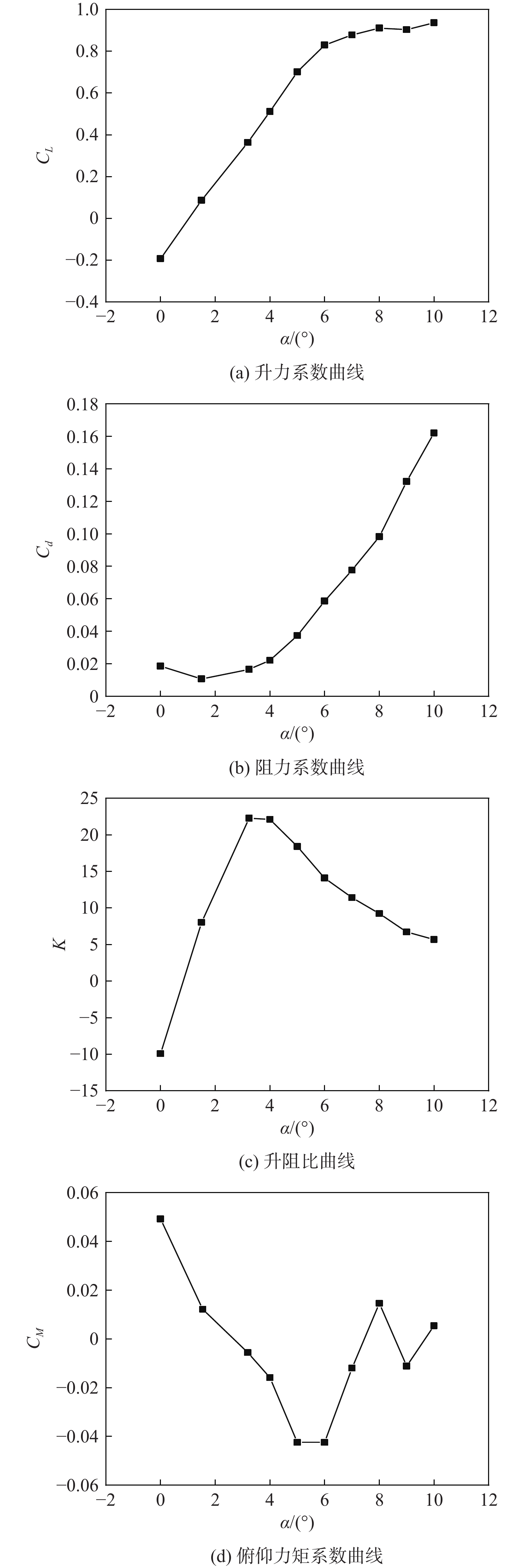
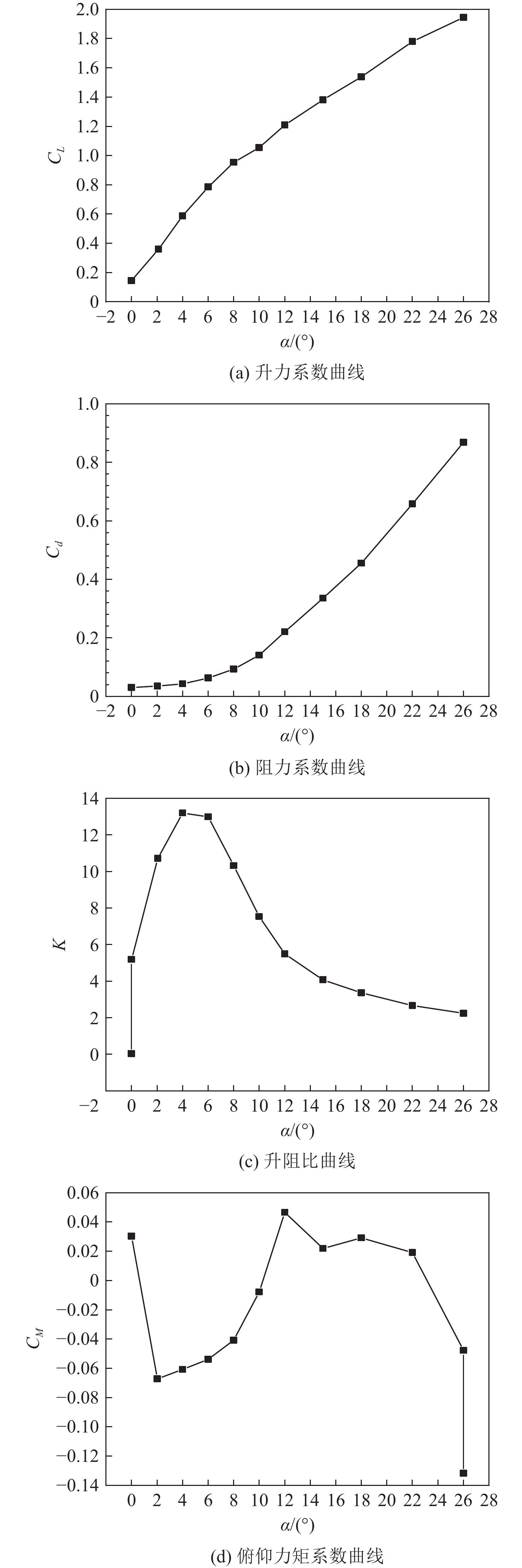
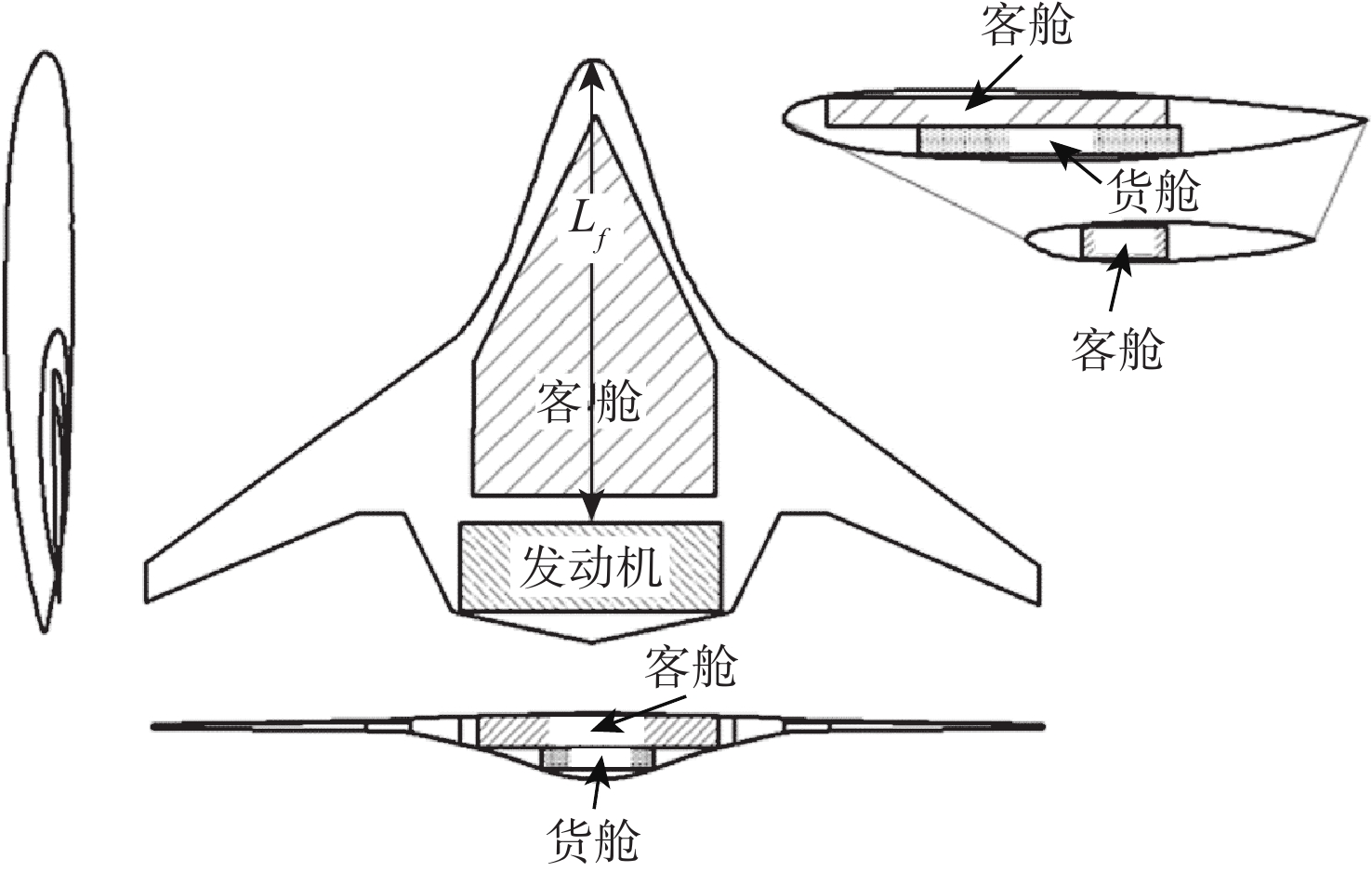
为探究风扇和核心机对于巡航气动特性的共同影响,以350座的翼身融合布局客机为研究对象,采用改变核心机展向位置,在此基础上改变动力系统弦向位置和展向位置的方法进行研究。研究结果表明:巡航状态下,核心机位置对于整流罩表面压力分布和飞机气动特性影响较小,动力系统后掠角为−12°,弦向位置为0.8时,升阻比可达22.39;在动力系统面积和流量不变的情况下,缩小其展向宽度会导致升力减小、阻力减小、升阻比下降、抬头力矩增加;飞机在巡航迎角3.2°下达到最大升阻比22.39,升力系数在起飞迎角10°下达到1.054 1,满足起飞升力系数要求。
Abstract:In order to investigate the joint influence of the fan and the core on the aerodynamic characteristics of the cruise, this paper takes a 350-seat blended-wing-body aircraft as the object of study, using the method of first changing the spanwise position of the core and, on this basis, later changing the chordwise and spanwise positions of the power system. The study results show that: Under cruise conditions, the core position has little influence on the pressure distribution on the fairing surface and the aerodynamic characteristics of the aircraft; under cruise conditions, the lift-to-drag ratio can reach 22.39 when the power system swept back angle is −12° and the chord position is 0.8; under the condition that the power system area and flow rate remain unchanged, reducing its spread width will lead to a reduction in lift, drag, lift-to-drag ratio and an increase in the lifting moment. The aircraft reaches a maximum lift-to-drag ratio of 22.39 at a cruise angle of attack of 3.2° and a lift coefficient of 1.0541 at a take-off angle of attack of 10°, which meets the take-off lift coefficient requirement.
-
Key words:
- blended-wing-body /
- power system /
- core /
- aerodynamic performance /
- chordwise and spanwise distribution
-

图 6 有无核心机构型上表面压力分布对比
Figure 6. Comparison of surface pressure distribution on models with and without core mechanism
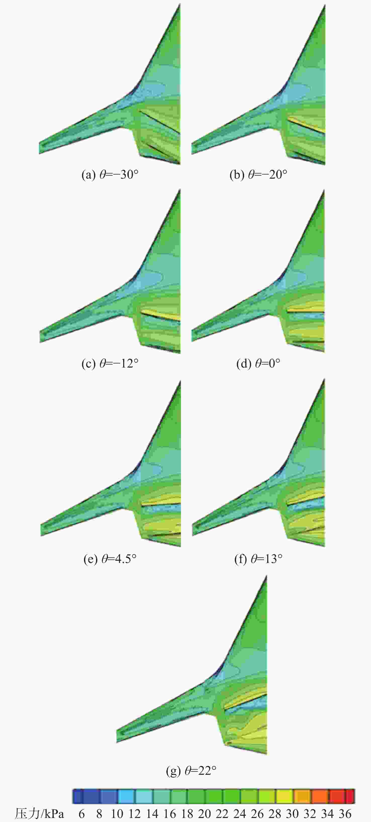
图 8 不同布置方案的上翼面压力分布对比
Figure 8. Comparison of pressure distribution on the upper airfoil for different arrangements
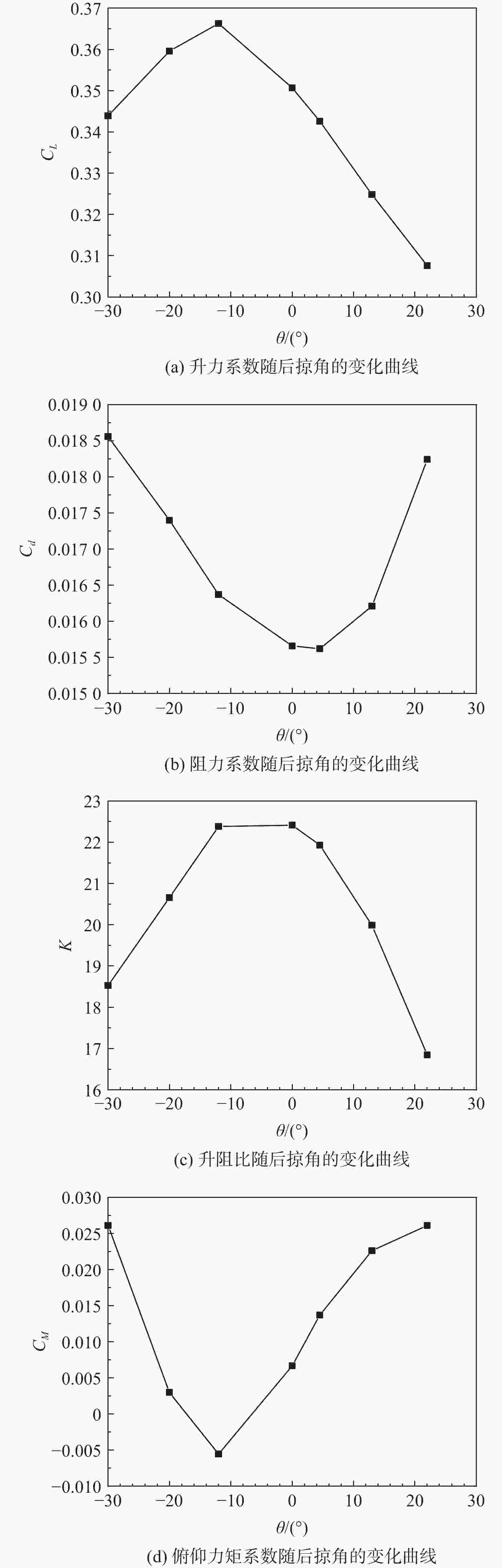
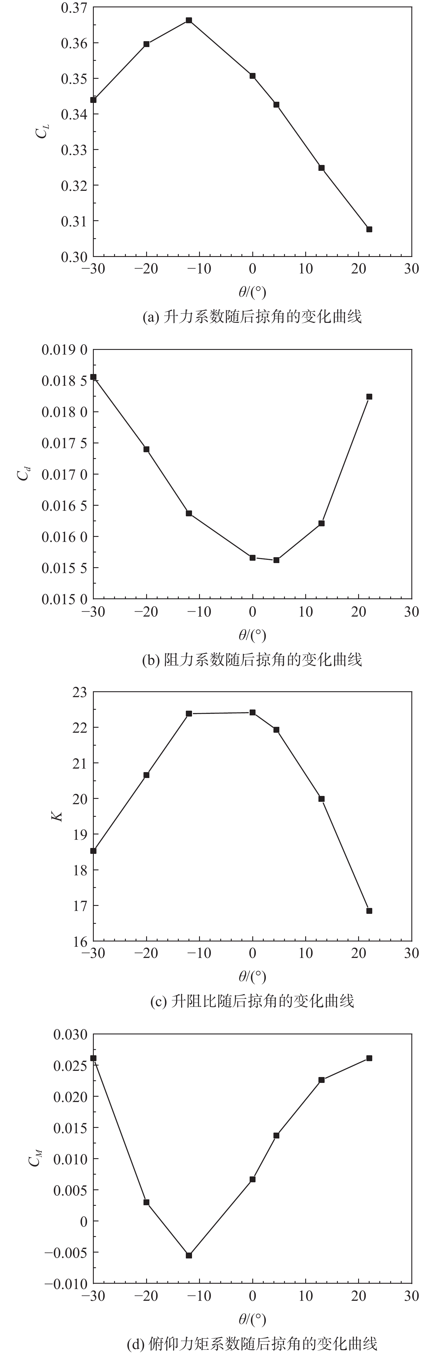
图 9 巡航气动参数随后掠角的变化曲线
Figure 9. Variation curves of cruise aerodynamic parameters with swept-back angle
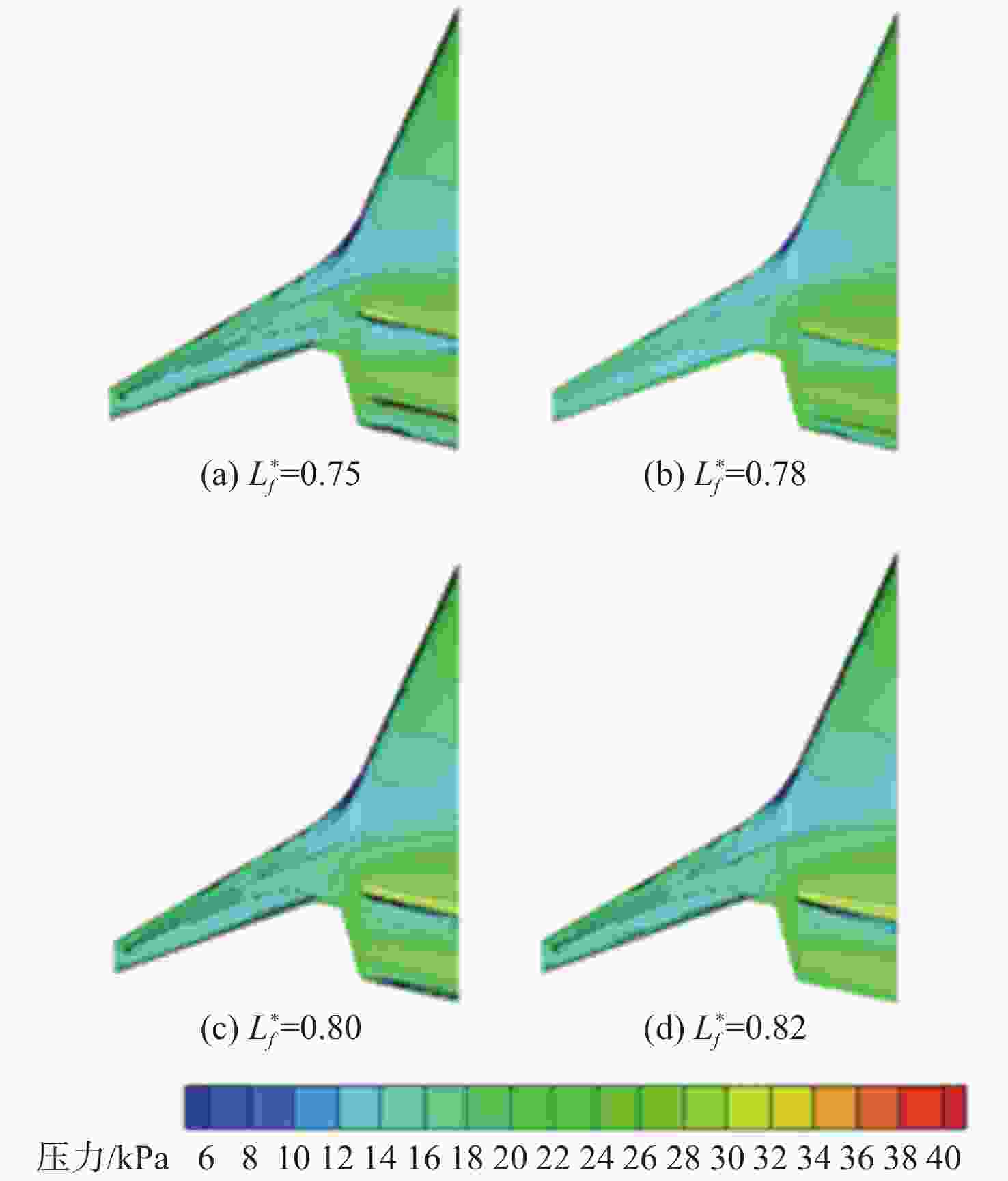
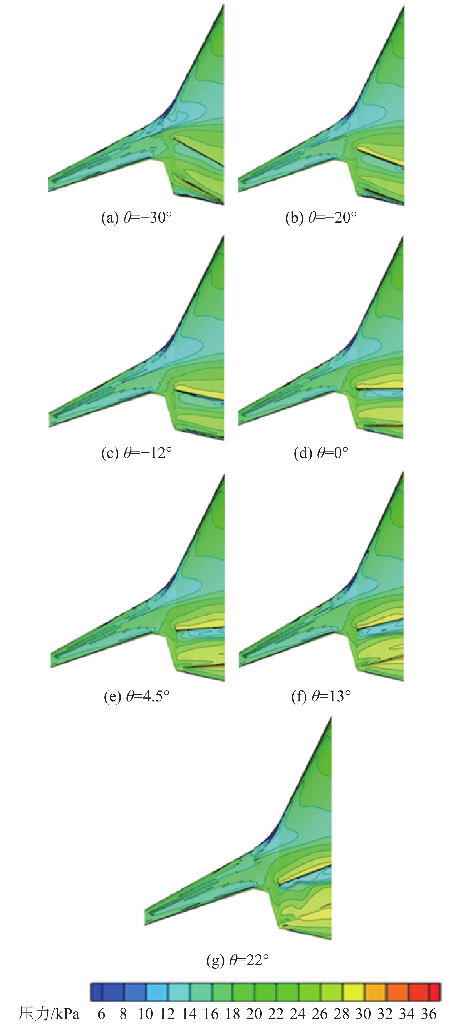
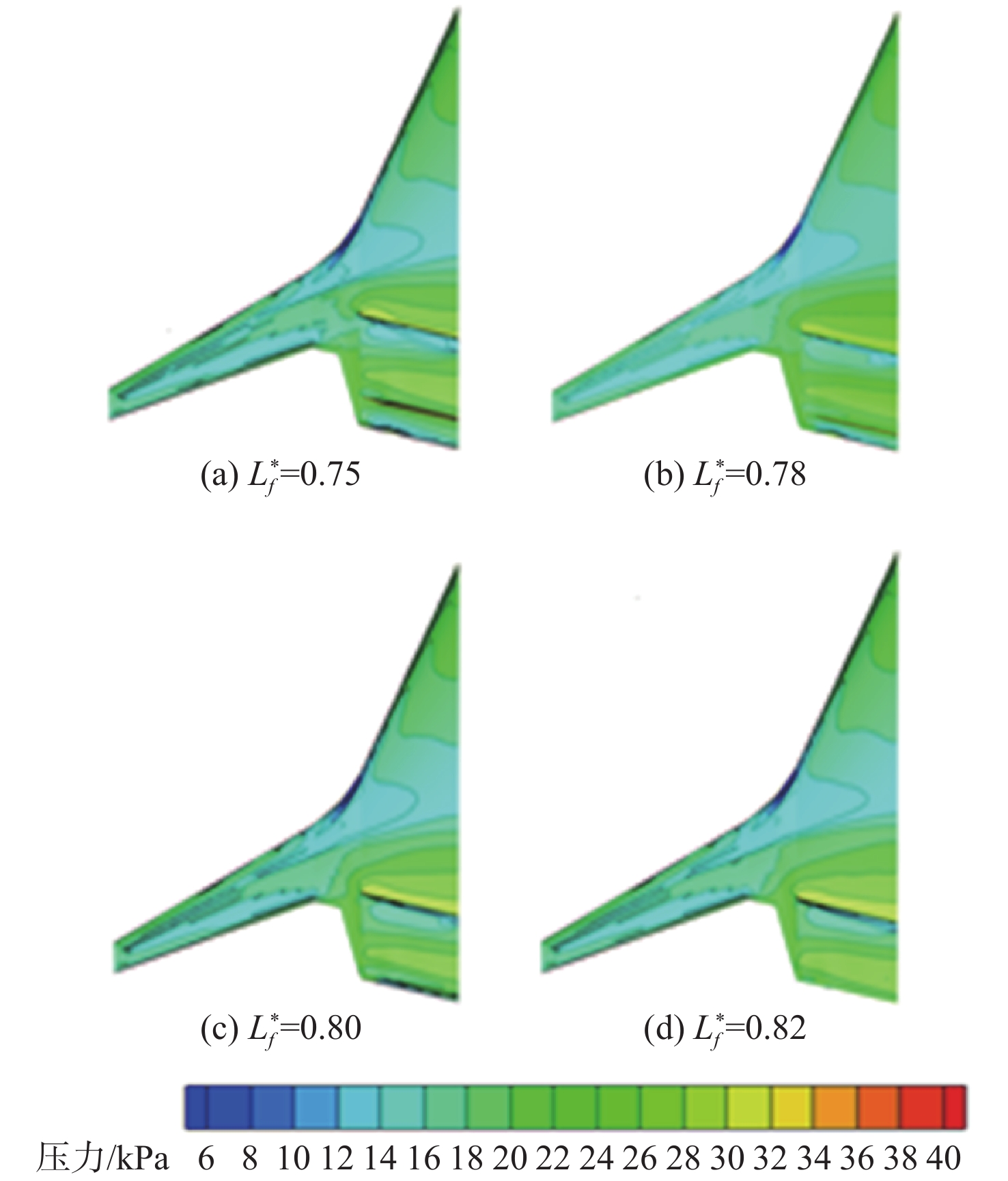
图 11 动力系统不同弦向位置方案上表面压力分布对比
Figure 11. Comparison of surface pressure distribution on different chordal positions for power system
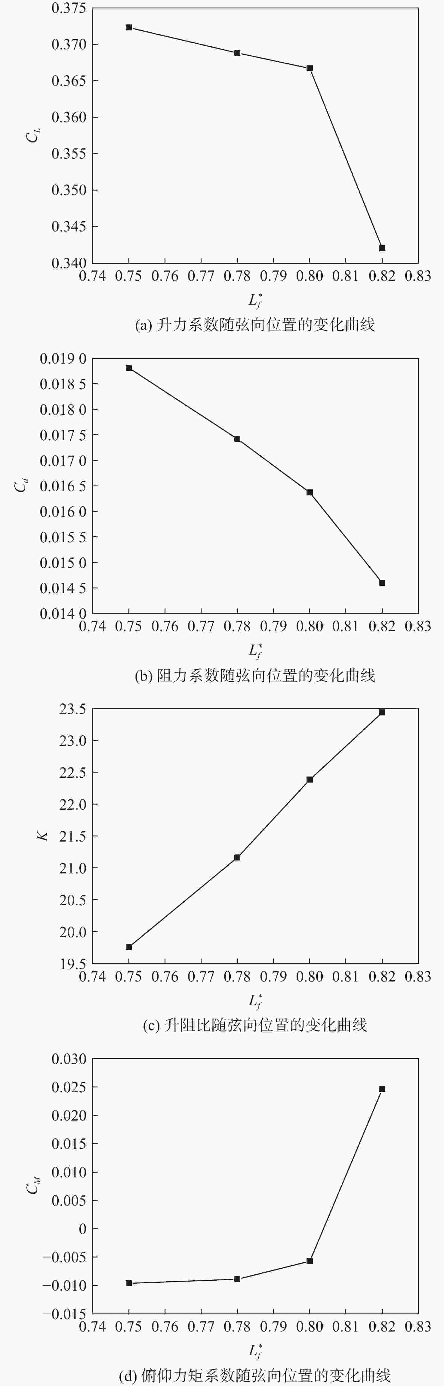
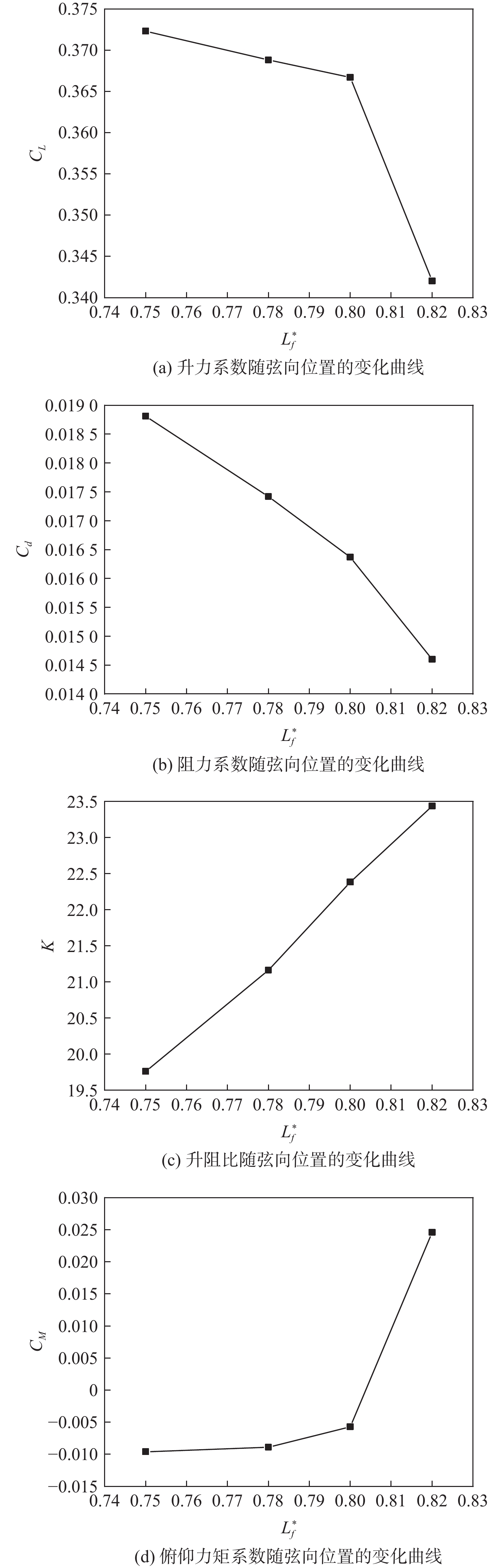
图 12 巡航气动参数随弦向位置的变化曲线
Figure 12. Variation curve of cruise aerodynamic parameters with chordal position
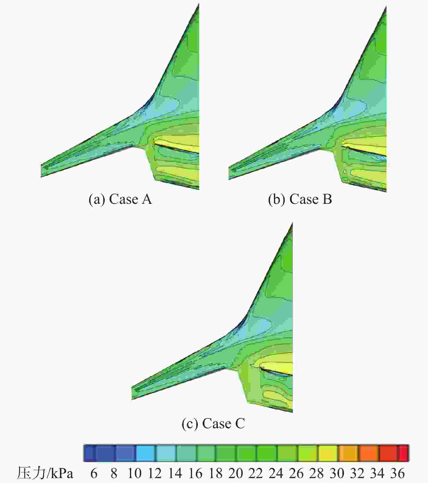
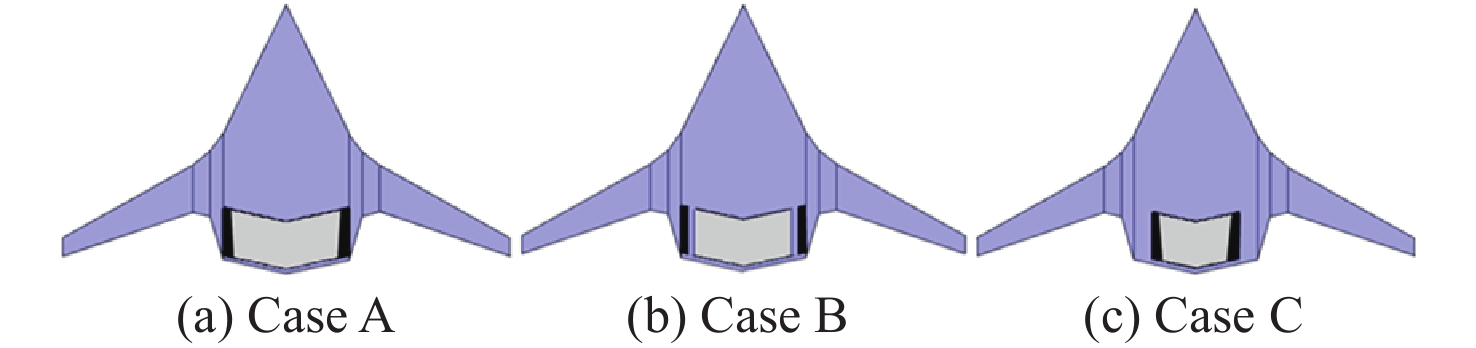
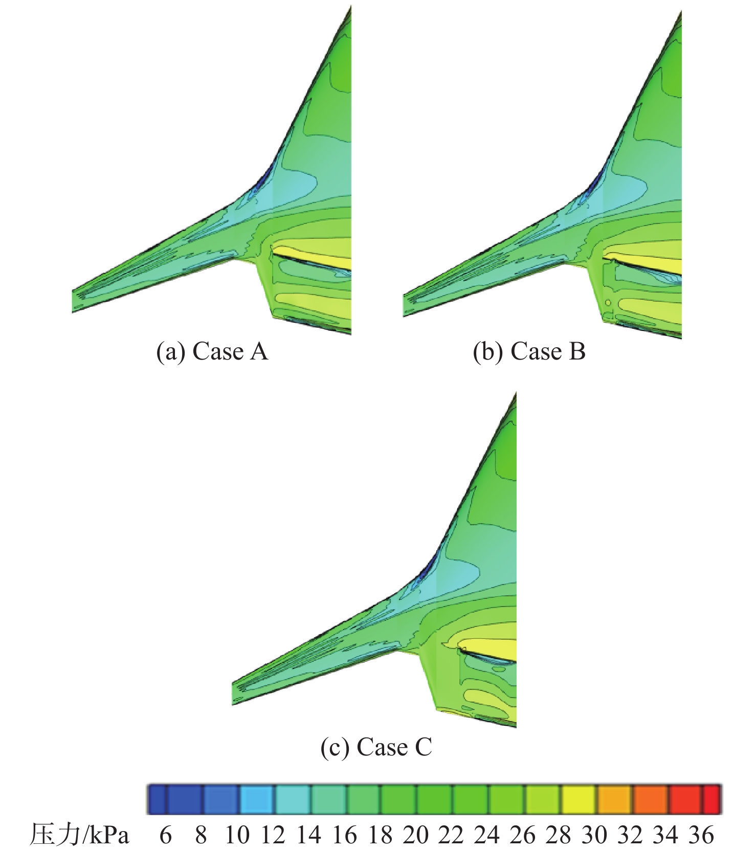
图 14 动力系统不同展向布置方案上翼面压力分布对比
Figure 14. Comparison of airfoil pressure distribution on different spanwise configurations of power system
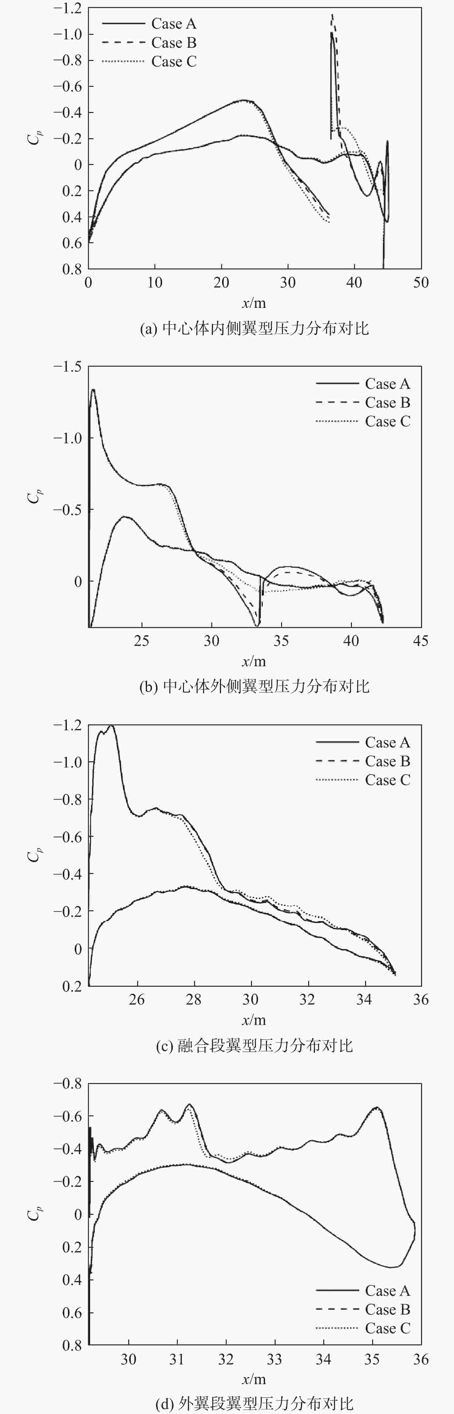
图 15 不同方案各特征截面翼型压力分布对比
Figure 15. Comparison of pressure distribution in each characteristic section airfoil
表 1 巡航状态风扇系统参数
Table 1. Fan system parameters of cruise state
参数 数值 进气道进口面积/m2 14 800 尾喷口出口面积/m2 11 000 尾喷口出口总温/K 0.85 质量流量/(kg·s−1) 1620 整流罩长度/m 7.939  下载: 导出CSV
表 2 起飞状态风扇系统参数
Table 2. Fan system parameters of takeoff state
参数 数值 进气道进口面积/m2 24.8 尾喷口出口面积/m2 13.53 尾喷口出口总温/K 322.5 质量流量/(kg·s−1) 4362 整流罩长度/m 7.939
下载: 导出CSV
表 3 巡航状态核心机参数
Table 3. Core parameters of cruise state
参数 数值 进气道进口面积/m2 1.46 尾喷口出口面积/m2 2 尾喷口出口总温/K 710 质量流量/(kg·s−1) 95.5 整流罩长度/m 7.939
下载: 导出CSV
表 4 起飞状态核心机参数
Table 4. Core parameters of takeoff state
参数 数值 进气道进口面积/m2 1.46 尾喷口出口面积/m2 2 尾喷口出口总温/K 820 质量流量/(kg·s−1) 256.92 整流罩长度/m 7.939
下载: 导出CSV
表 5 不同
${\boldsymbol{y}}_{{\bf{max}} }^ {\boldsymbol{+}}$ 网格的计算结果比较(Ma=0.85, α=3.2°)Table 5. Comparison of calculation results of different
${\boldsymbol{y}}_{{\bf{max}} }^ {\boldsymbol{+}}$ grids (Ma=0.85, α=3.2°)网格数量/104 第1层网格高度 $y_{\max }^ + $ CL Cd 310 1×10⁻³ 200 0.3669 0.01775 310 1×10⁻⁴ 20 0.3640 0.01812 310 1×10⁻⁵ 2 0.3625 0.01820 310 1×10⁻⁶ 0.2 0.3627 0.01821
下载: 导出CSV
表 6 不同网格数量计算结果比较(Ma=0.85, α=3.2°)
Table 6. Comparison of calculation results of different overall grid densities (Ma=0.85, α=3.2°)
网格数量/104 第1层网格高度 $y_{\max }^ + $ CL Cd 100 1×10⁻⁵ 2 0.3530 0.01964 190 1×10⁻⁵ 2 0.3607 0.01882 310 1×10⁻⁵ 2 0.3625 0.01820 430 1×10⁻⁵ 2 0.3637 0.01807
下载: 导出CSV
表 7 巡航和起飞状态下的计算条件
Table 7. Calculation conditions in cruise and take-off
飞行
条件高度/
m马赫数 流量系数
MFR静压/
Pa静温/
K密度/
(kg·m−3)起飞 0 0.265 1.594 101325 288.2 1.2249 巡航 11000 0.85 0.714 22700 216.7 0.3639
下载: 导出CSV
表 8 核心机不同布置方案计算结果
Table 8. Calculation results for different core arrangements
构型 CL Cd CM K Case0 0.3620 0.01660 0.0071 21.81 Case1 0.3428 0.01561 0.0136 21.95 Case2 0.3359 0.01529 0.0190 21.98 Case3 0.3375 0.01566 0.0170 21.55 Case4 0.3413 0.01566 0.0149 21.79 Case5 0.3452 0.01583 0.0121 21.81
下载: 导出CSV
表 9 动力系统不同后掠角计算结果
Table 9. Calculation results for different swept-back angles of power system
后掠角θ/(°) CL Cd CM K −30 0.3444 0.01857 0.0261 18.54 −20 0.3598 0.01742 0.0030 20.66 −12 0.3668 0.01638 −0.0056 22.39 0 0.3510 0.01566 0.0068 22.42 4.5 0.3427 0.01561 0.0136 21.95 13 0.3249 0.01622 0.0227 20.03 22 0.3077 0.01826 0.0263 16.85
下载: 导出CSV
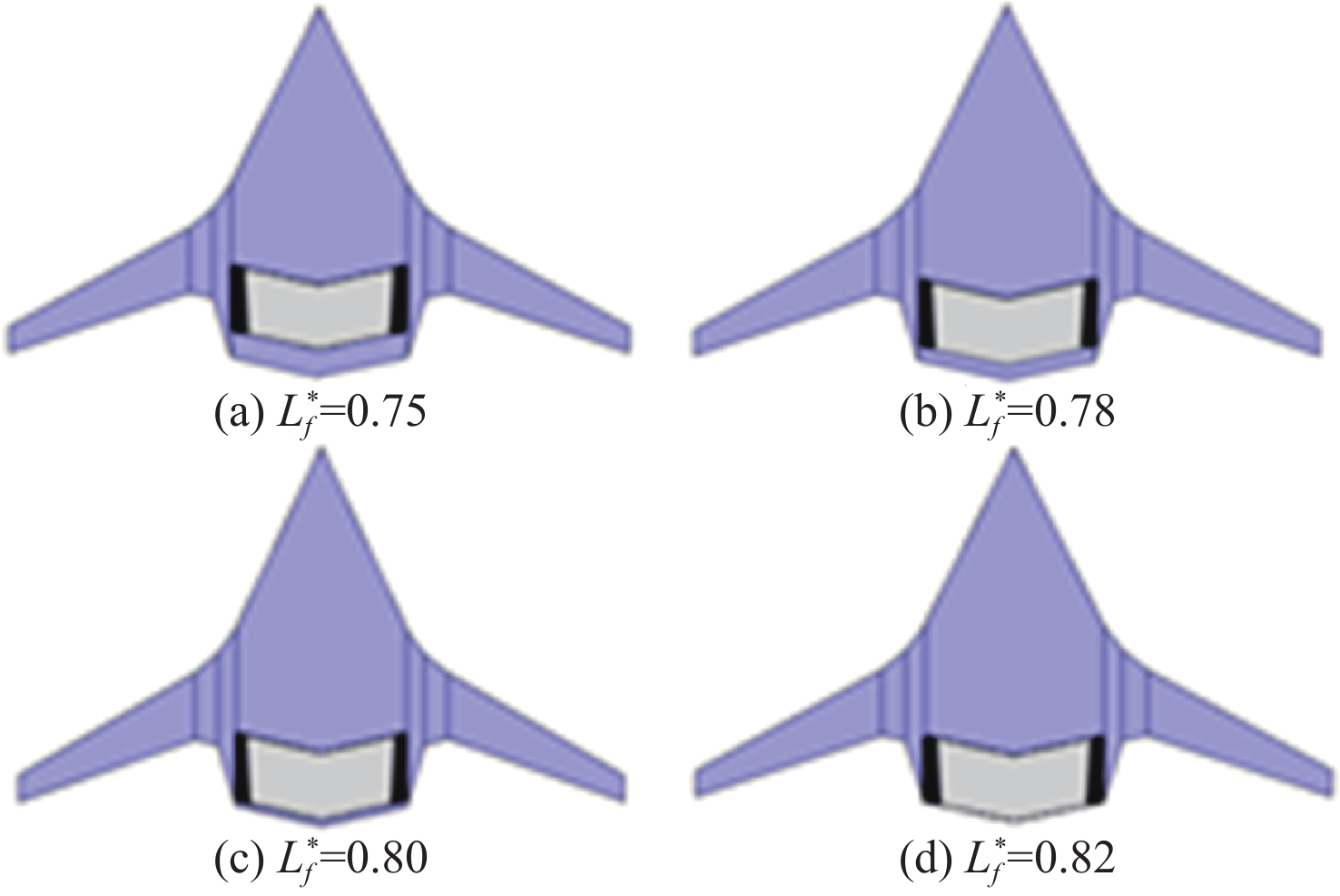
表 10 动力系统不同弦向位置方案计算结果
Table 10. Calculation results for different chordal position of power system
构型$L^*_f $ CL Cd CM K 0.75 0.3723 0.01883 −0.0095 19.77 0.78 0.3688 0.01742 −0.0090 21.18 0.80 0.3668 0.01638 −0.0056 22.39 0.82 0.3421 0.01459 0.0249 23.45
下载: 导出CSV
表 11 动力系统不同展向布置方案计算结果
Table 11. Calculation results for different spanwise configurations of power system
构型 CL Cd CM K Case A 0.3668 0.01638 −0.0056 22.39 Case B 0.3644 0.01649 −0.0027 22.09 Case C 0.3340 0.01549 0.0177 21.56
下载: 导出CSV
-
[1] LIEBECK R H. Design of the blended wing body subsonic transport[J]. Journal of Aircraft, 2004, 41(1): 10-25. doi: 10.2514/1.9084 [2] 李晓勇, 李栋成, 周涛. 翼身融合飞机的空气动力学研究进展简介[J]. 民用飞机设计与研究, 2006(4): 1-9. doi: 10.3969/j.issn.1674-9804.2006.04.001LI X Y, LI D C, ZHOU T. Brief introduction of aerodynamic research progress of wing-body fusion aircraft[J]. Civil Aircraft Design and Research, 2006(4): 1-9(in Chinese). doi: 10.3969/j.issn.1674-9804.2006.04.001 [3] 吴峰. 翼身融合体飞机气动外形设计及分析[D]. 南昌: 南昌航空大学, 2017: 1-5.WU F. Pneumatic shape design and pneumatic analysis of wing body fusion aircraft[D]. Nanchang: Nanchang Hangkong University, 2017: 1-5 (in Chinese) . [4] 闫万方, 吴江浩, 张艳来. 分布式推进关键参数对BWB飞机气动特性影响[J]. 北京航空航天大学学报, 2015, 41(6): 1055-1065. doi: 10.13700/j.bh.1001-5965.2014.0390YAN W F, WU J H, ZHANG Y L. Effects of distributed propulsion crucial variables on aerodynamic performance of blended wing body aircraft[J]. Journal of Beijing University of Aeronautics and Astronautics, 2015, 41(6): 1055-1065(in Chinese). doi: 10.13700/j.bh.1001-5965.2014.0390 [5] 邢宇. 桁架支撑机翼布局客机总体设计的综合分析与优化[D]. 南京: 南京航空航天大学, 2018: 2-3.XING Y. Integrated analysis and optimization in conceptual design of airliners with truss-braced wing configuration[D]. Nanjing: Nanjing University of Aeronautics and Astronautics, 2018: 2-3 (in Chinese). [6] SCHETZ J A, HOSDER S, DIPPOLD V, et al. Propulsion and aerodynamic performance evaluation of jet-wing distributed propulsion[J]. Aerospace Science and Technology, 2010, 14(1): 1-10. doi: 10.1016/j.ast.2009.06.010 [7] HILEMAN J I. Airframe design for silent fuel-efficient aircraft[J]. Journal of Aircraft, 2010, 47(3): 956-969. doi: 10.2514/1.46545 [8] KAWAI R T , FRIEDMAN D M , SERRANO L. Blended wing body (BWB) boundary layer ingestion (BLI) inlet configuration and system studies: 106478812 [R]. Washington, D. C: National Aeronautics and Space Administration, 2006: 1-26. [9] DIEDRICH A, HILEMAN J, TAN D, et al. Multidisciplinary design and optimization of the silent aircraft[C]//44th AIAA Aerospace Sciences Meeting and Exhibit. Reston: AIAA, 2006: 1323. [10] RE R J. Longitudinal aerodynamic characteristics and wing pressure distributions of a blended-wing-body configuration at low and high reynolds numbers: 117728409 [R]. Washington, D. C: National Aeronautics and Space Administration, 2005: 1-103. [11] RODRIGUEZ D L. Multidisciplinary optimization method for designing boundary-layer-ingesting inlets[J]. Journal of Aircraft, 2009, 46(3): 883-894. doi: 10.2514/1.38755 [12] REIST T A, ZINGG D W. Aerodynamic shape optimization of a blended-wing-body regional transport for a short range mission[C]// 31st AIAA Applied Aerodynamics Conference. Reston: AIAA, 2013: 2414. [13] LYU Z J, MARTINS J R R A. Aerodynamic shape optimization of a blended-wing-body aircraft[C]//51st AIAA Aerospace Sciences Meeting Including the New Horizons Forum and Aerospace Exposition. Reston: AIAA, 2013: 283. [14] 熊永臻. 分布式动力翼身融合构型气动性能研究[J]. 现代商贸工业, 2019, 40(11): 213-215. doi: 10.19311/j.cnki.1672-3198.2019.11.105XIONG Y Z. Study on aerodynamic performance of distributed dynamic wing-body fusion configuration[J]. Modern Business Trade Industry, 2019, 40(11): 213-215(in Chinese). doi: 10.19311/j.cnki.1672-3198.2019.11.105 [15] 陈青, 昂海松, 胡银彪. 某型无人机的三维重建与气动性能分析[J]. 南昌航空工业学院学报(自然科学版), 2003, 17(4): 32-35.CHEN Q, ANG H S, HU Y B. The research and application of unmanned aerial vehicle’s 3D rebuilded method[J]. Journal of Nanchang Institute of Aeronautical Technology, 2003, 17(4): 32-35(in Chinese). [16] 戴浩, 余雄庆. 翼身融合飞机参数化几何模型[J]. 飞机设计, 2012, 32(2): 11-14. doi: 10.19555/j.cnki.1673-4599.2012.02.003DAI H, YU X Q. Parametric geometric model for blended wing body configuration[J]. Aircraft Design, 2012, 32(2): 11-14(in Chinese). doi: 10.19555/j.cnki.1673-4599.2012.02.003 -

 下载:
下载:


 点击查看大图
计量
- 文章访问数: 327
- HTML全文浏览量: 57
- PDF下载量: 36
- 被引次数: 0
