


Stiffness optimization of M-shaped boom based on radial basis function surrogate model
-
摘要:
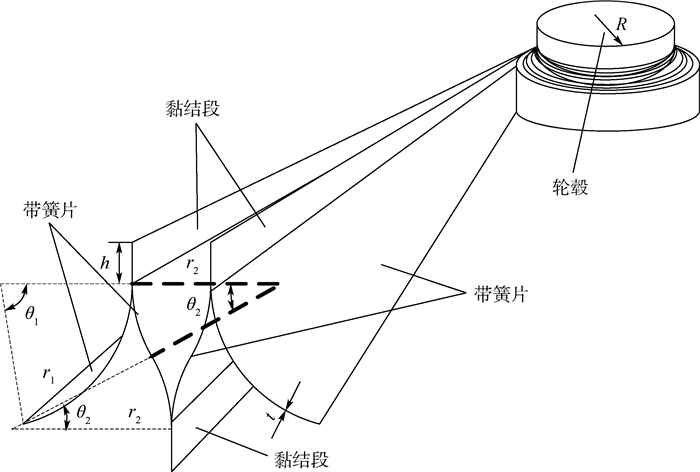
在航天任务的执行中, 超弹性杆主要用于大型空间可展天线和太阳帆等展开和支撑。为了提高超弹性杆在展开状态下的刚度, 提出了一种新型M形超弹性杆, 并对M形超弹性杆的刚度进行了研究。采用ABAQUS建立M形超弹性杆的弯曲、压缩和扭转的有限元模型, 利用显示动力学法对屈曲过程进行非线性数值模拟。采用全因子法进行实验设计, 利用径向基函数(RBF)建立M形超弹性杆屈曲过程性能参数的代理模型。以弯曲刚度、扭转刚度和压缩刚度为优化目标, 以质量为约束, 选取黏结段长度和内侧带簧片圆心角为自变量建立优化模型。采用粒子群(PSO)算法进行M形超弹性杆参数优化, 得到最优刚度下, 黏结段长度为7.894 5 mm, 圆心角为26°, 并且得到刚度随其变化规律。
Abstract:In the execution of space missions, the hyper-elastic boom is mainly used in the deployment and support of large space deployable antennas and solar sails. In order to improve the supporting effect of the hyper-elastic boom in the state of deployment, the stiffness of the M-shaped hyper-elastic boom (M boom) with different sizes was studied. By using ABAQUS, the M boom's bending, compression, and torsion finite element models were created, and an explicit dynamic method was used to carry out a nonlinear numerical simulation of the M boom's buckling process.The bending stiffness, torsional stiffness and compression stiffness were taken as optimization objectives, the mass as constraint, and the cross-section arc length and radius as independent variables to establish the optimization model. The full factor method was used to design the experiment, the radial basis function (RBF) was used to establish the buckling surrogate model of the M boom, using the particle swarm optimization (PSO) algorithm to perform parameter optimization of the M boom. The ideal values for the length of bonding segment and the central angle were 7.894 5 mm and 26°, and the variation rule of stiffness with the length of bonding segment and the central angle was obtained.
-
Key words:
- composite material /
- deployable structure /
- M-shaped boom /
- radial basis function /
- optimization
-

图 4 M形杆绕x轴弯曲的应力云图和力矩曲线
Figure 4. Cloud chart of stress and bending moment curve of M boom around x-axis

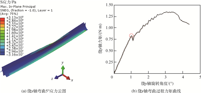
图 5 M形杆绕y轴弯曲的应力云图和力矩曲线
Figure 5. Cloud chart of stress and bending moment curve of M boom around y-axis

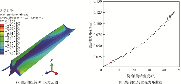
图 6 M形杆绕z轴扭转的应力云图和力矩曲线
Figure 6. Cloud chart of stress and torsion moment curve of M boom around z-axis

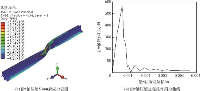
图 7 M形杆沿z轴压缩的应力云图和反作用力曲线
Figure 7. Stress cloud diagram and reaction force curves of M boom compressed along z-axis
表 1 T800材料属性
Table 1. Material properties of T800
材料属性 T800 黏结胶 纵向弹性模量E1/MPa 150 000 横向弹性模量E2=E3/MPa 7 000 60 000 剪切模量G12=G13/MPa 7 000 面内剪切模量G23/MPa 4 500 泊松比υ 0.3 0.3 密度ρ /(kg·m-3) 2 500 1 600  下载: 导出CSV
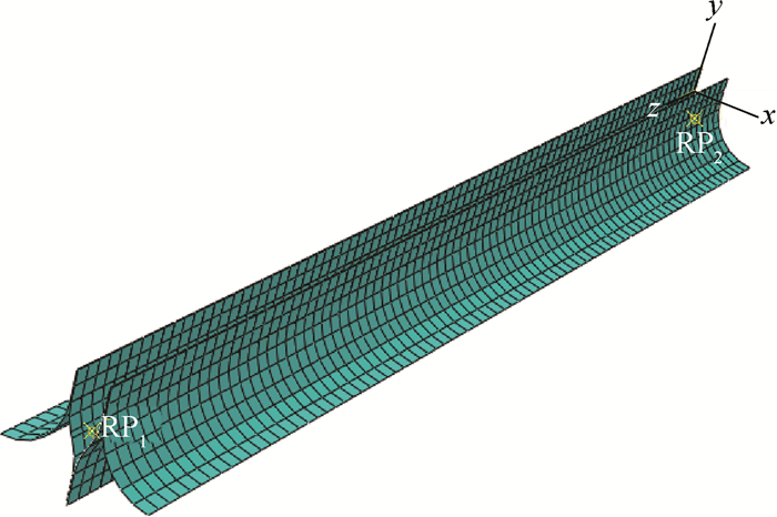
表 2 参考点RP2在不同情况下的边界条件
Table 2. Reference point RP2 boundary conditions under different conditions
约束 绕x轴弯曲 绕y轴弯曲 绕z轴扭转 沿z轴正向压缩 UX 0 释放约束 释放约束 释放约束 UY 释放约束 0 释放约束 释放约束 UZ 释放约束 释放约束 0 施加位移载荷 RX 施加旋转载荷 0 0 0 RY 0 施加旋转载荷 0 0 RZ 0 0 施加旋转载荷 0
下载: 导出CSV
表 3 样本点
Table 3. Sample points
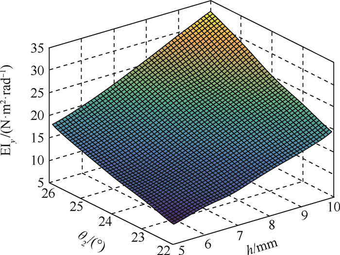
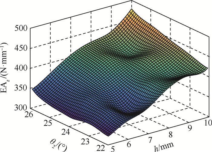
序号 h/mm θ2/(°) EIx(h, θ2)/(N·m2·rad-1) EIy(h, θ2)/(N·m2·rad-1) GJz(h, θ2)/(N·m2·rad-1) EAz(h, θ2)/(N·mm-1) 1 5 22 16.525 8.800 0.022 318.836 2 5 23 17.764 10.718 0.026 322.861 3 5 24 19.018 12.579 0.031 314.631 4 5 25 20.672 14.756 0.037 322.566 5 5 26 21.779 17.296 0.044 341.485 6 6 22 20.299 10.467 0.028 342.641 7 6 23 21.683 12.250 0.031 352.375 8 6 24 23.548 13.527 0.036 359.440 9 6 25 24.680 16.322 0.045 354.424 10 6 26 26.529 19.273 0.051 349.309 11 7 22 24.826 11.736 0.030 362.863 12 7 23 26.121 14.097 0.038 336.068 13 7 24 28.263 15.904 0.043 386.556 14 7 25 30.448 18.814 0.049 387.839 15 7 26 31.960 21.919 0.059 417.498 16 8 22 31.014 13.979 0.035 390.809 17 8 23 24.585 16.280 0.039 391.156 18 8 24 25.897 19.031 0.050 389.042 19 8 25 35.451 22.181 0.059 412.499 20 8 26 36.913 25.155 0.068 398.496 21 9 22 34.444 16.144 0.042 418.356 22 9 23 28.561 18.814 0.050 396.581 23 9 24 30.862 21.860 0.057 421.409 24 9 25 39.797 24.364 0.072 404.325 25 9 26 43.121 24.267 0.079 430.254 26 10 22 42.957 18.604 0.051 417.984 27 10 23 42.714 21.545 0.057 426.818 28 10 24 46.798 24.402 0.064 440.339 29 10 25 47.374 28.437 0.081 454.123 30 10 26 51.486 32.035 0.094 470.183
下载: 导出CSV
表 4 径向基函数代理模型核函数中常数c的取值
Table 4. Values of constant c in kernel function of RBFs surrogate model
目标量 c值 EIx 1 EIy 0.3 GJz 0.3 EAz 0.3
下载: 导出CSV
表 5 误差测试样本点
Table 5. Sample points of relative errors
序号 h/mm θ2/(°) 有限元结果 代理模型结果 相对误差E/% EIx(h, θ2)/(N·m2·rad-1) EIy(h, θ2)/(N·m2·rad-1) EIx(h, θ2)/(N·m2·rad-1) EIy(h, θ2)/(N·m2·rad-1) EIx(h, θ2) EIy(h, θ2) 1 6 26 26.529 19.273 26.120 19.259 -1.542 -0.073 2 7 24 28.263 15.904 27.329 16.169 -3.305 1.666 3 7 26 31.960 21.919 32.612 22.091 2.040 0.785 4 8 22 31.014 13.979 29.105 14.097 -6.155 0.844 5 8 26 36.913 25.155 38.292 25.342 3.736 0.743 序号 h/mm θ2/(°) 有限元结果 代理模型结果 相对误差E/% GJz(h, θ2)/(N·m2·rad-1) EAz(h, θ2)/(N·mm-1) GJz(h, θ2)/(N·m2·rad-1) EAz(h, θ2)/(N·mm-1) GJz(h, θ2) EAz(h, θ2) 1 6 26 0.051 4 349.309 0.051 0 367.851 -0.778 5.308 2 7 24 0.043 4 386.556 0.042 9 366.866 -1.152 -5.094 3 7 26 0.059 3 417.498 0.058 4 400.586 -1.518 -4.051 4 8 22 0.034 8 390.809 0.035 2 395.578 1.149 1.220 5 8 26 0.068 2 398.496 0.067 7 420.565 -0.733 5.538
下载: 导出CSV
表 6 目标量和约束量的比例因子和权重
Table 6. Scale factors and weights of objective and constraint quantities
目标量 Si Wi EIx 1 1.2 EIy 1 2 GJz 1 1 000 EAz 1 0.1 M0 1 1.5
下载: 导出CSV
表 7 Pareto设计点
Table 7. Pareto points of design
序号 h/mm θ2/(°) M0/g EIx(h, θ2)/(N·m2·rad-1) EIy(h, θ2)/(N·m2·rad-1) GJz(h, θ2)/(N·m2·rad-1) EAz(h, θ2)/(N·mm-1) 1 7.970 7 25.727 7 24.932 7 37.814 4 24.341 7 0.065 0 415.960 8 2 7.894 5 26 24.911 4 37.794 9 24.994 1 0.066 6 419.362 2
下载: 导出CSV
表 8 最优设计点
Table 8. Optimal point of design
结果 对应刚度 数值 有限元 EIx(h, θ2)/(N·m2·rad-1) 36.286 2 EIy(h, θ2)/(N·m2·rad-1) 24.828 4 GJz(h, θ2)/(N·m2·rad-1) 0.065 1 EAz(h, θ2)/(N·mm-1) 430.808 6 代理模型 EIx(h, θ2)/(N·m2·rad-1) 37.794 9 EIy(h, θ2)/(N·m2·rad-1) 24.994 1 GJz(h, θ2)/(N·m2·rad-1) 0.066 6 EAz(h, θ2)/(N·mm-1) 419.362 2 相对误差E/% EIx(h, θ2) 4.16 EIy(h, θ2) 0.67 GJz(h, θ2) 2.30 EAz(h, θ2) -2.66
下载: 导出CSV
-
[1] SICKINGER C, HERBECK L. Deployment strategies, analyses and tests for the CFRP booms of a solar sail[C]//European Conference on Spacecraft Structures, Materials and Mechanical Testing, 2002. [2] HU Y, CHEN W J, GAO J F, et al. A study of flattening process of deployable composite thin-walled lenticular tubes under compress and tension[J]. Composite Structure, 2017, 168: 164-177. doi: 10.1016/j.compstruct.2017.02.029 [3] BAI J B, CHEN D, XIONG J J, et al. Folding analysis for thin-walled deployable composite[J]. Acta Astronautica, 2019, 159: 622-636. doi: 10.1016/j.actaastro.2019.02.014 [4] BANIK J, MUTPHEY T. Performance validation of the triangular rollable and collapsible mast[C]//24th Annual AIAA/USU Conferenceon Small Satellites, 2010: 1-8. [5] YANG H, LIU R Q, WANG Y, et al. Experiment and multiobjective optimization design of tape-spring hinges[J]. Structural and Multidisciplinary Optimization, 2015, 51(6): 1373-1384. doi: 10.1007/s00158-014-1205-9 [6] STABILE A, LAURENZI S. Coiling dynamic analysis of thin-walled composite deployable boom[J]. Composite Structures, 2014, 113: 429-436. doi: 10.1016/j.compstruct.2014.03.043 [7] HOSKIN A, VIQUERAT A, AGLIETTI G S. Tip force during blossoming of coiled deployable booms[J]. International Journal of Solids and Structures, 2017, 118-119: 58-69. doi: 10.1016/j.ijsolstr.2017.04.023 [8] MALLIKARACHCHI H M Y C, PELLEGRINO S. Deployment dynamics of ultrathin composite booms with tape-spring hinges[J]. Journal of Spacecraft and Rockets, 2014, 51(2): 604-613. doi: 10.2514/1.A32401 [9] MALLIKARACHCHI H M Y C, PELLEGRINO S. Design of ultrathin composite self-deployable booms[J]. Journal of Spacecraft and Rockets, 2014, 51(6): 1811-1821. doi: 10.2514/1.A32815 [10] MALLIKARACHCHI H M Y C. Predicting mechanical properties of thin woven carbon fiber reinforced laminates[J]. Thin-Walled Structures, 2019, 135: 297-305. doi: 10.1016/j.tws.2018.11.016 [11] CHU Z Y, LEI Y A. Design theory and dynamic analysis of a deployable boom[J]. Mechanism and Machine Theory, 2014, 71: 126-141. doi: 10.1016/j.mechmachtheory.2013.09.009 [12] CHU Z Y, LEI Y A, LI D. Dynamics and robust adaptive control of a deployable boom for a space probe[J]. Acta Astronautica, 2014, 97: 138-150. doi: 10.1016/j.actaastro.2014.01.009 [13] CAI J G, ZHOU Y, WANG X Y, et al. Dynamic analysis of a cylindrical boom based on Miura Origami[J]. Steel and Composite Structures, 2018, 28(5): 607-615. [14] ANGELETTI F, GASBARRI P, SABATINI M. Optimal design and robust analysis of a net of active devices for microvibration control of an on-orbit large space antenna[J]. Acta Astronautica, 2019, 164: 241-253. doi: 10.1016/j.actaastro.2019.07.028 [15] CHEN W J, FANG G Q, HU Y. An experimental and numerical study of flattening and wrapping process of deployable composite thin-walled lenticular tubes[J]. Thin-Walled Structures, 2017, 111: 38-47. doi: 10.1016/j.tws.2016.11.009 [16] BESSA M A, PELLEGRINO S. Design of ultra-thin shell structures in the stochastic post-buckling range using Bayesian machine learning and optimization[J]. International Journal of Solids and Structures, 2018, 139-140: 174-188. doi: 10.1016/j.ijsolstr.2018.01.035 [17] BESSA M A, BOSTANABAD R, LIU Z, et al. A framework for data-driven analysis of materials under uncertainty: Countering the curse of dimensionality[J]. Computer Methods in Applied Mechanics and Engineering, 2017, 320: 633-667. doi: 10.1016/j.cma.2017.03.037 [18] ROYBAL F A, BANIK J A, MURPHEY T W. Development of an elastically deployable boom for tensioned planar structures: AIAA 2007-1838[R]. Reston: AIAA, 2007. [19] YANG H, LU F S, GUO H W, et al. Design of a new N-shape composite ultra-thin deployable boom in the post-buckling range using response surface method and optimization[J]. IEEE Access, 2019, 7: 129659-129665. doi: 10.1109/ACCESS.2019.2934744 [20] 谢进德. 代理模型技术的研究及其在汽车抗撞性中的应用[D]. 长沙: 湖南大学, 2013.XIE J D. Research on surrogate model technology and its application in vehicle crashworthiness[D]. Changsha: Hunan University, 2013(in Chinese). -

 下载:
下载:


 点击查看大图
计量
- 文章访问数: 328
- HTML全文浏览量: 120
- PDF下载量: 22
- 被引次数: 0
