


Simulation modeling methodology for broadband conducted immunity quantization of analog and analog-digital hybrid chips
-
摘要:
针对目前模拟与模数混合芯片在射频(RF)传导敏感性建模方法集成电路传导抗扰度模型(ICIM-CI)中存在模型非线性特性不足、预测与实际电路在特定干扰条件下的表现存在较大偏差及无法开展级联量化敏感性仿真等问题,提出一种基于多谐波失真理论的模拟和模数混合芯片传导敏感度ICIM-CI改进建模方法,并集成电路传导抗扰度模型-非线性敏感行为模块(ICIM-CI-NIB)。该方法通过在敏感度行为(IB)模块中引入多谐波非线性参数,显著提升了传导敏感模型的非线性特性,将ICIM-CI模型从二值判定结果模型改进为具有非线性量化输出响应的级联仿真模型。通过采用ICIM-CI-NIB方法,能够快速生成芯片的传导敏感性频域宽带模型,具备在宽频大功率干扰注入下的高精度传导敏感性仿真模型,并支持级联仿真。通过典型模拟与模数混合芯片的实测结果显示:相较于ICIM-CI方法,所提方法归一化均方根误差(NMSE)提高了18.5 dB,同时建模时间减少了约98%。
Abstract:There are issues with the current analog and analog-digital hybrid chip in radio frequency (RF) conduction sensitivity modeling method models of integrated circuits for RF integrated circuit immunity model-conducted immunity modeling (ICIM-CI). These issues include the model's lack of nonlinear characteristics, significant discrepancies between the prediction and the actual circuits' performance under particular interference conditions, and the inability to perform cascade quantization sensitivity simulation. The study proposes an improved model, integrated circuit immunity model-conducted immunity modeling-nonlinear immunity behavior (ICIM-CI-NIB), an improved modeling method for ICIM-CI with analog and analog-digital hybrid chip conduction sensitivity based on the theory of multi-harmonic distortion, which significantly improves the nonlinear characteristics of the conduction sensitivity model by introducing the multi-harmonic nonlinear parameter into the immunity behavior(IB)module, which improves the ICIM-CI model from the binary judgment result model to the cascaded quantized sensitivity simulation with nonlinear quantized output response of the cascade simulation model. By adopting the ICIM-CI-NIB method, it can quickly generate the frequency domain broadband model of the chip's conduction sensitivity, have a high-precision conduction sensitivity simulation model under the wide-band large-power interference injection, and support the cascade simulation. The observed results on a common analog and analog-digital hybrid chip demonstrate that this method reduces the modeling time by approximately 98% while improving the normalized mean square error (NMSE) by 18.5 dB when compared to the ICIM-CI method.
-
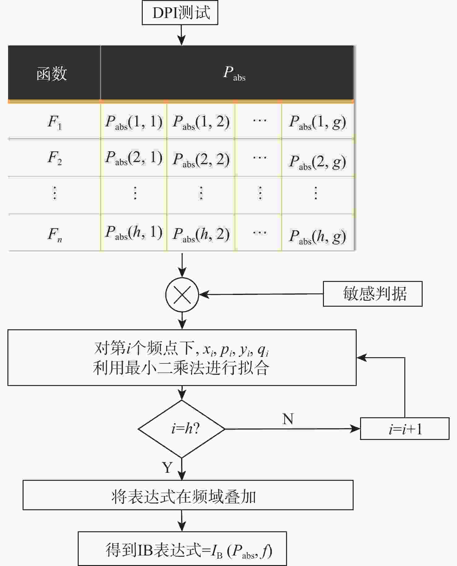
图 2 IB原始方法函数建立流程
Figure 2. Flowchart of function establishment for the traditional IB method
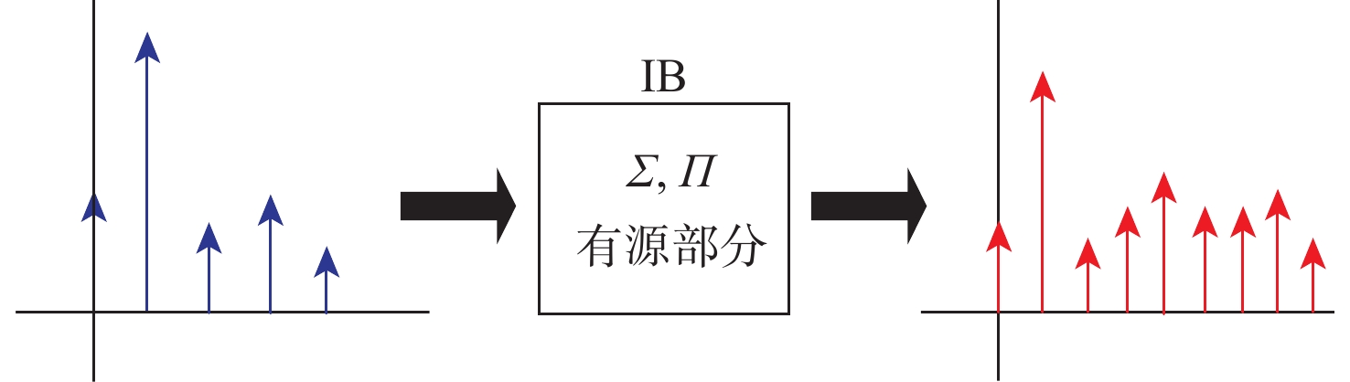
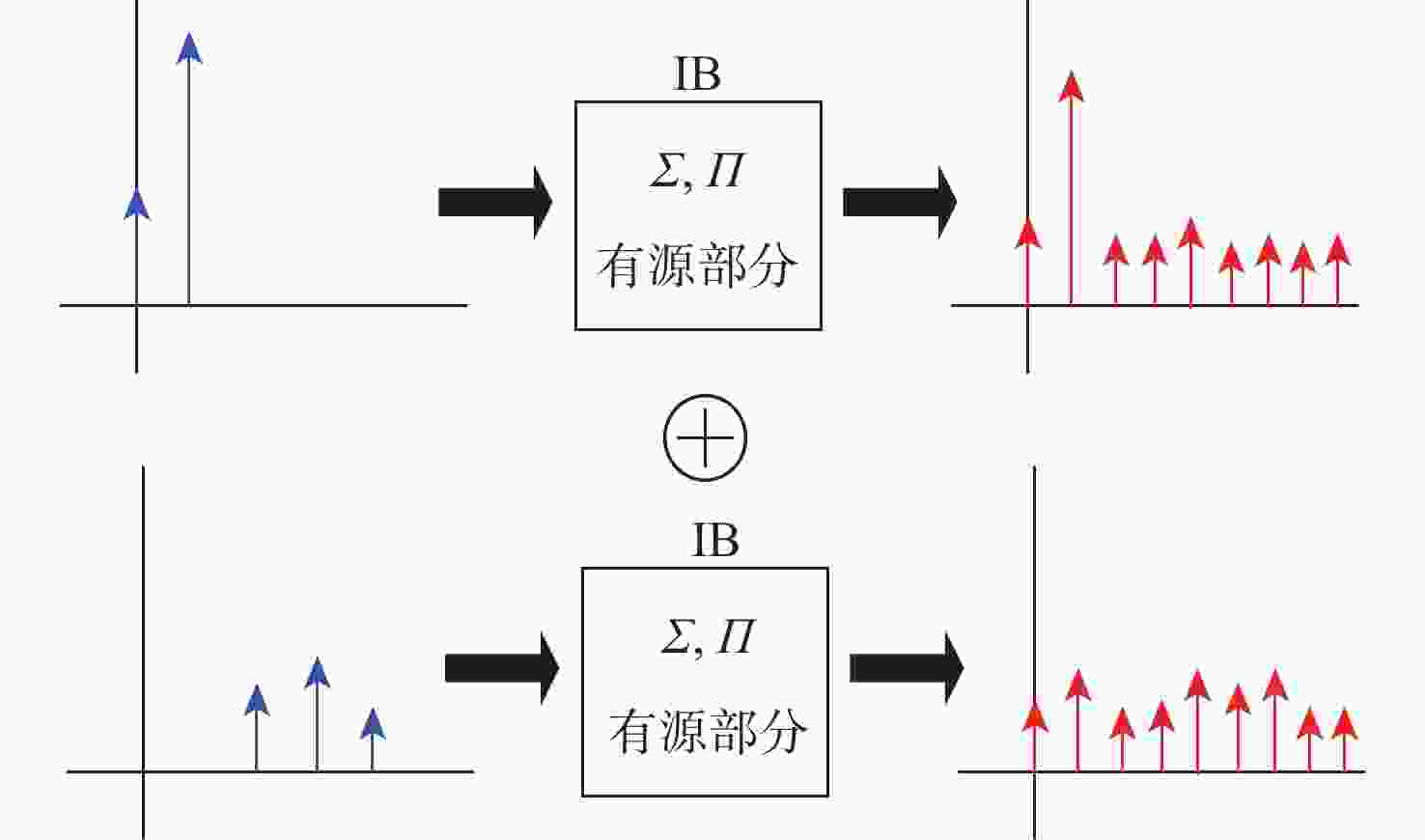
图 5 分为简单的非线性映射和线性非解析映射
Figure 5. Divided into simple nonlinear mapping and linear non-analytic mapping
图 7 芯片输出受到轻微扰动时(干扰注入−25 dBm时)
Figure 7. Slight jitter in output waveform when subjected to −25 dBm interference, not exceeding tolerance requirements
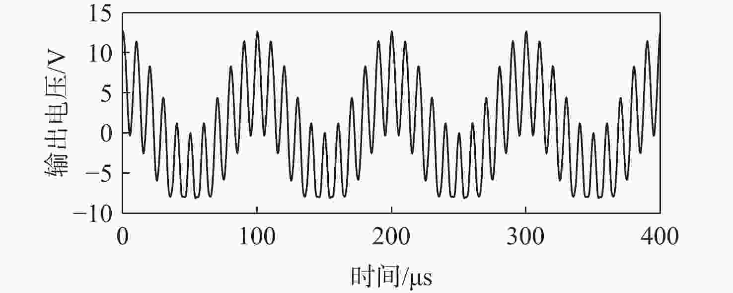
图 8 芯片输出受到较大扰动时(干扰注入0 dBm时)
Figure 8. Jittery output waveforms exceeding tolerance requirements when subjected to 0 dBm interference
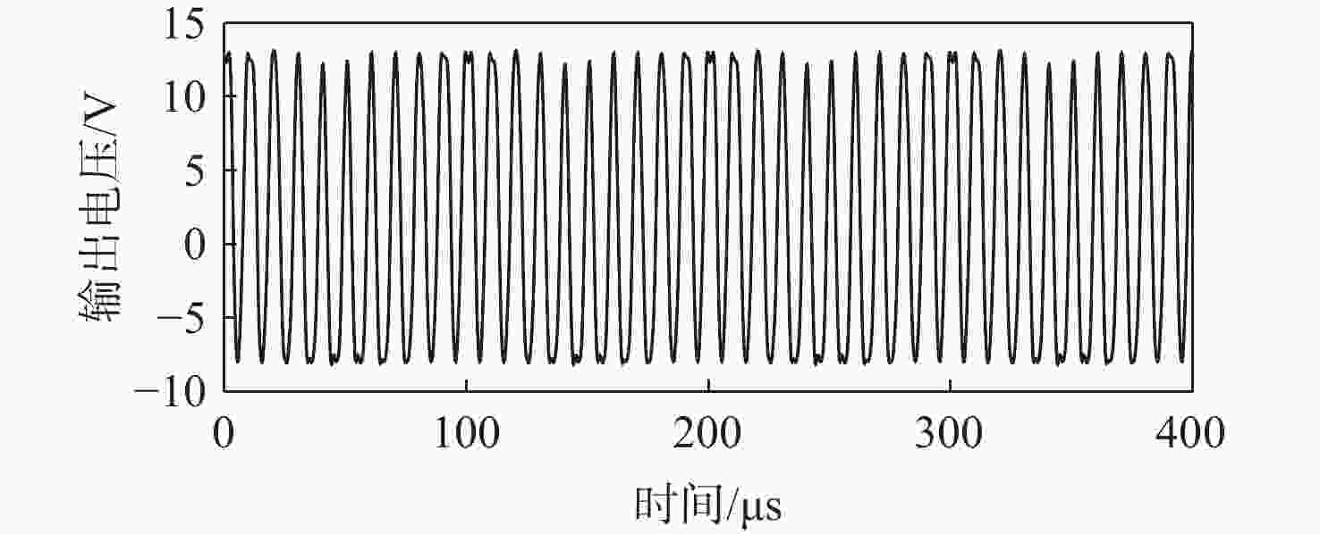
图 9 芯片输出严重受扰时(干扰注入10 dBm时)
Figure 9. Severe jitter in output waveform exceeding tolerance requirement when subjected to 10 dBm interference
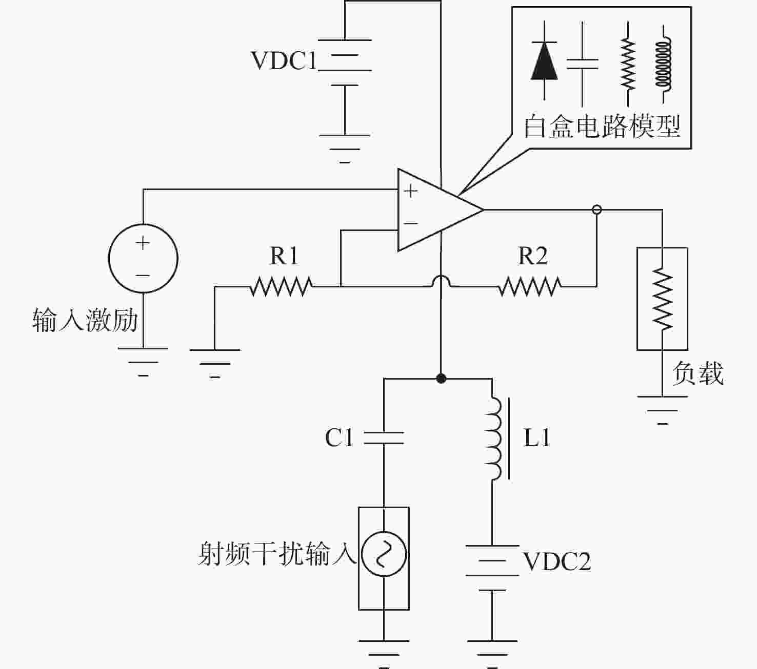
图 10 对电源端口V −提取注入抗干扰模型
Figure 10. Extraction of injection immunity models for power terminal V −
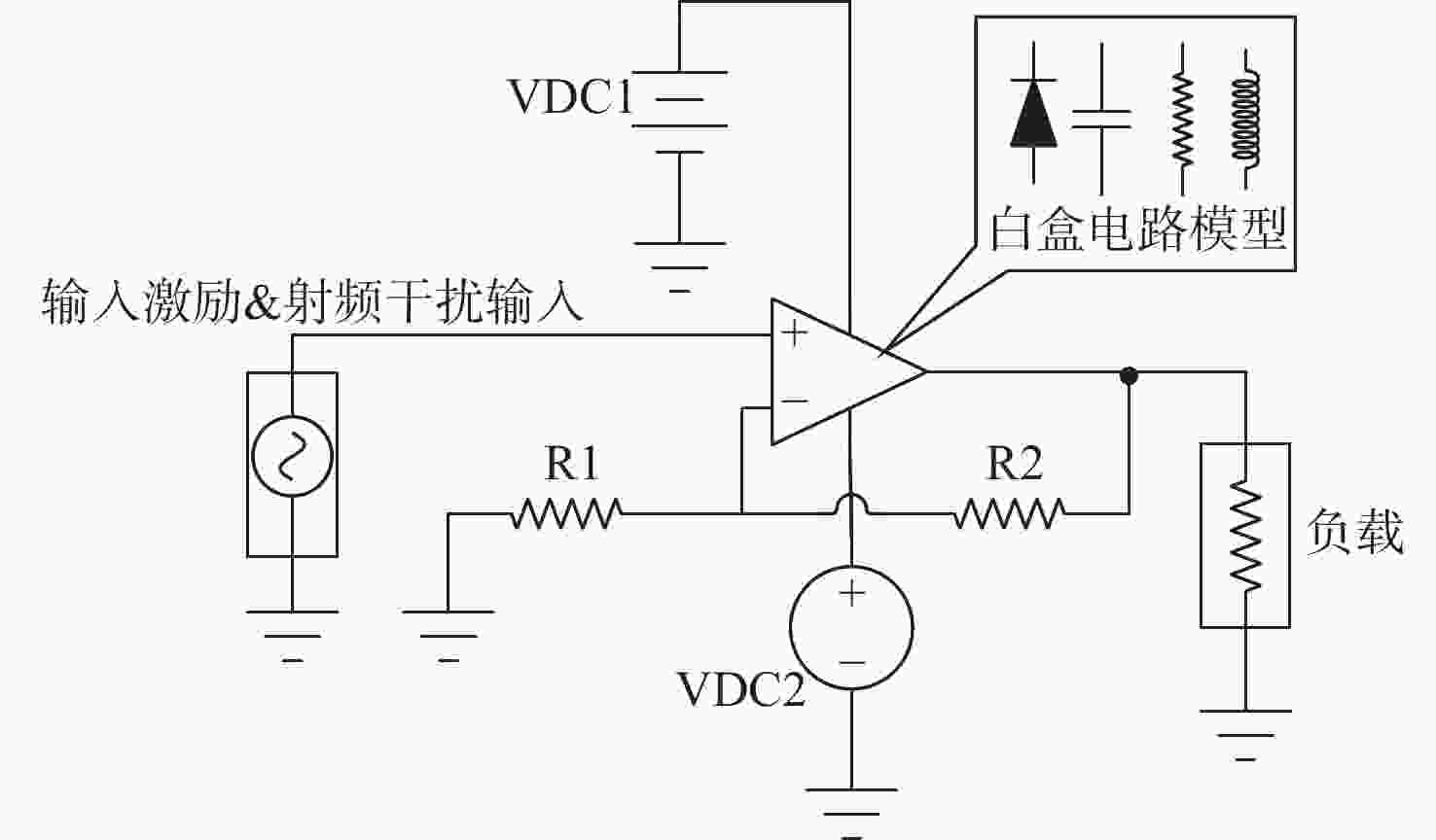
图 11 对输入端$V_{\mathrm{in}}^+ $提取注入抗干扰模型
Figure 11. Extraction of injected immunity model for input terminal $V_{\mathrm{in}}^+ $
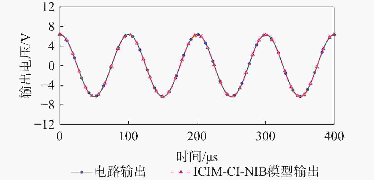
图 12 芯片正常工作时仿真模型输出与实际输出结果对比
Figure 12. Comparison of simulation model output and actual output results during normal operation of chip
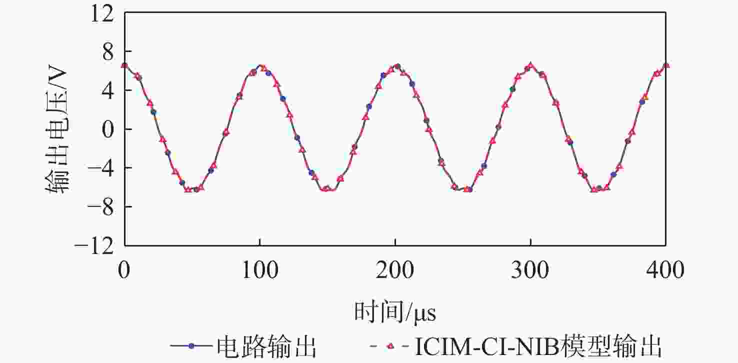
图 13 芯片输出受到轻微扰动时(干扰注入−25 dBm时)仿真模型输出与实际输出结果对比
Figure 13. Comparison of simulation model output and actual output when slight jitter occurs at the chip output (interference injection −25 dBm)
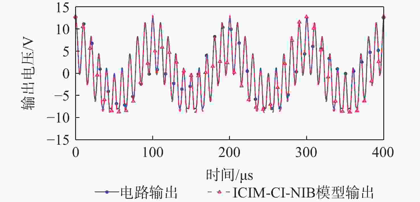
图 14 芯片输出受到较大扰动时(干扰注入0 dBm时)仿真模型输出与实际输出结果对比
Figure 14. Comparison of simulation model output and actual output results when severe jitter occurs at chip output (when interference is injected at 0 dBm)
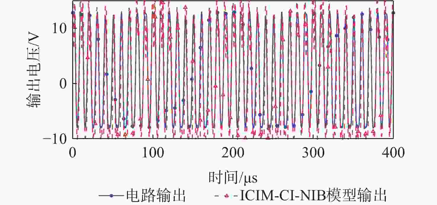
图 15 芯片输出严重受扰时(干扰注入10 dBm时)仿真模型输出与实际输出结果对比
Figure 15. Comparison of simulation model output and actual output results when chip output is severely disturbed (interference injection at 10 dBm)
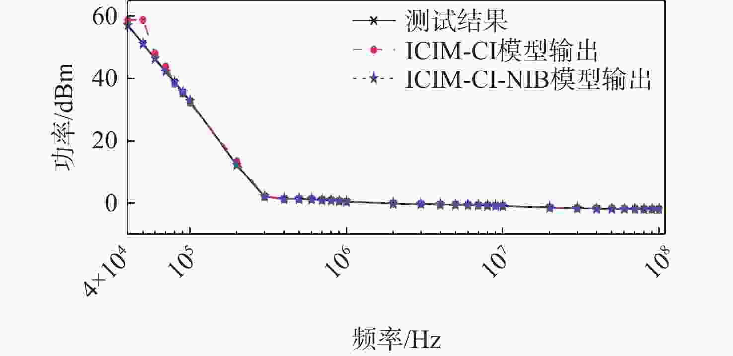
图 16 2种建模方法的敏感性预测与实际输出结果的比较
Figure 16. Comparison of sensitivity predictions of two modeling methods with actual output results
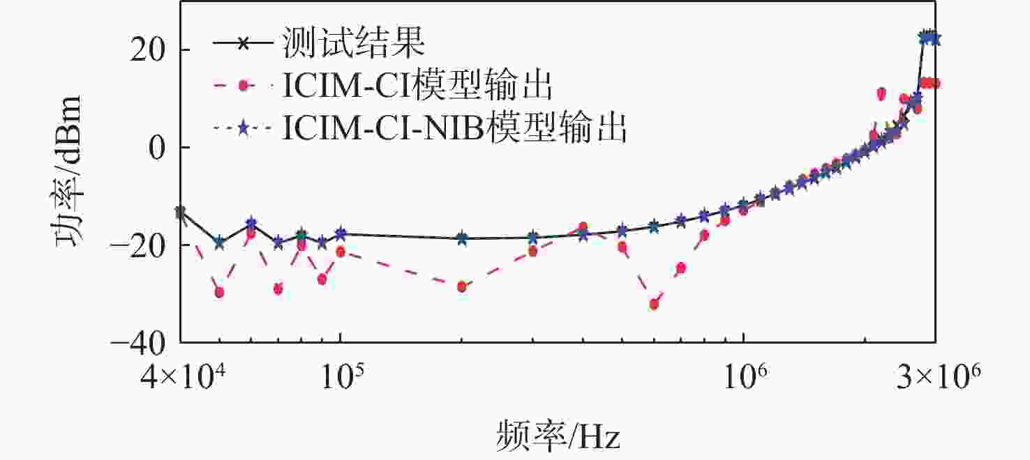
图 17 2种建模方法的敏感性预测与实际输出结果的比较(V+端口,敏感判据为ΔVoutp-p≤10%)
Figure 17. Comparison of the sensitivity prediction of two modeling methods with actual output results (at V+port, immunity criterion at ΔVoutp-p≤10%)
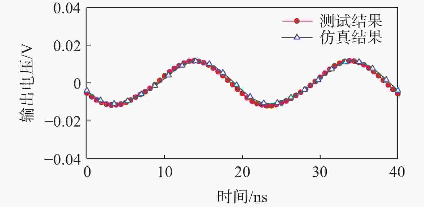
图 20 f=50 MHz,PF=−5 dBm时,测试结果和仿真结果的对比
Figure 20. Comparison of test and simulation results at f=50MHz, PF=−5 dBm
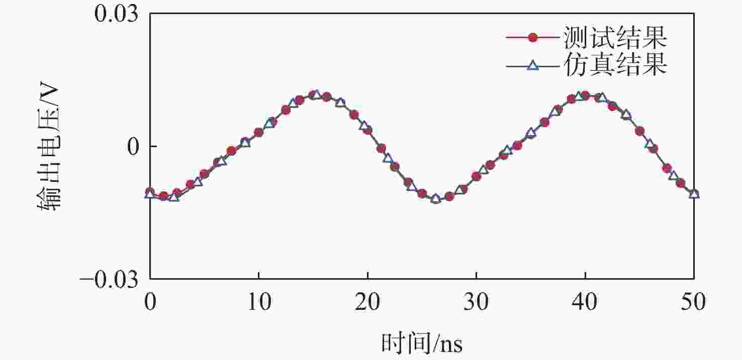
图 21 f=40 MHz,PF=−5 dBm时,测试结果和仿真结果的对比
Figure 21. Comparison of test and simulation results at f=40 MHz, PF=−5 dBm
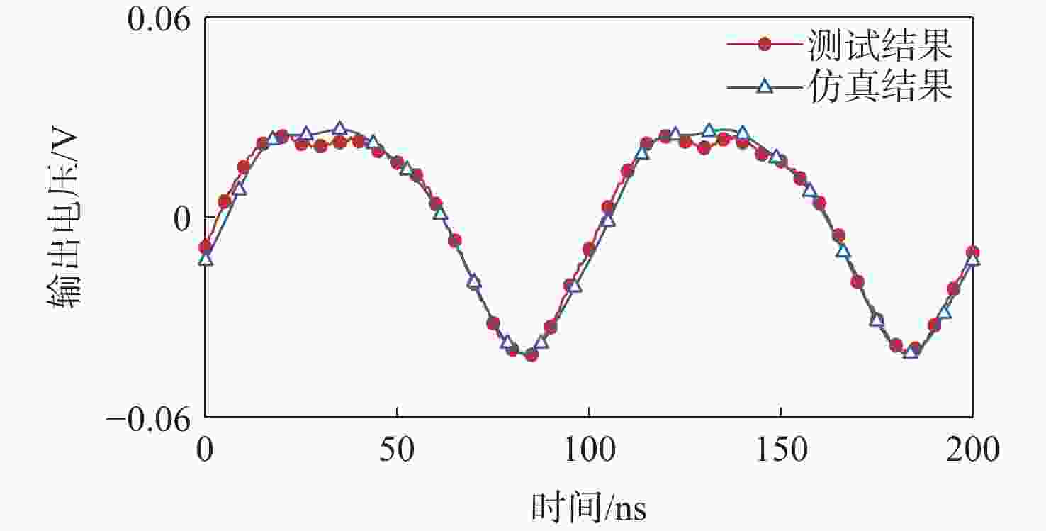
图 22 f=10 MHz,PF=0 dBm时,测试结果和仿真结果的对比
Figure 22. Comparison of test and simulation results at f=10 MHz, PF=0 dBm
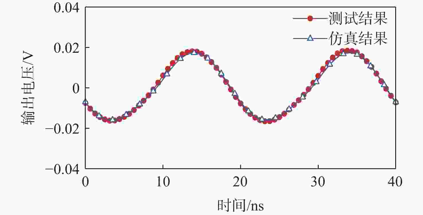
图 23 f=50 MHz,PF=0 dBm时,测试结果和仿真结果的对比
Figure 23. Comparison of test and simulation results at f=50 MHz, PF=0 dBm
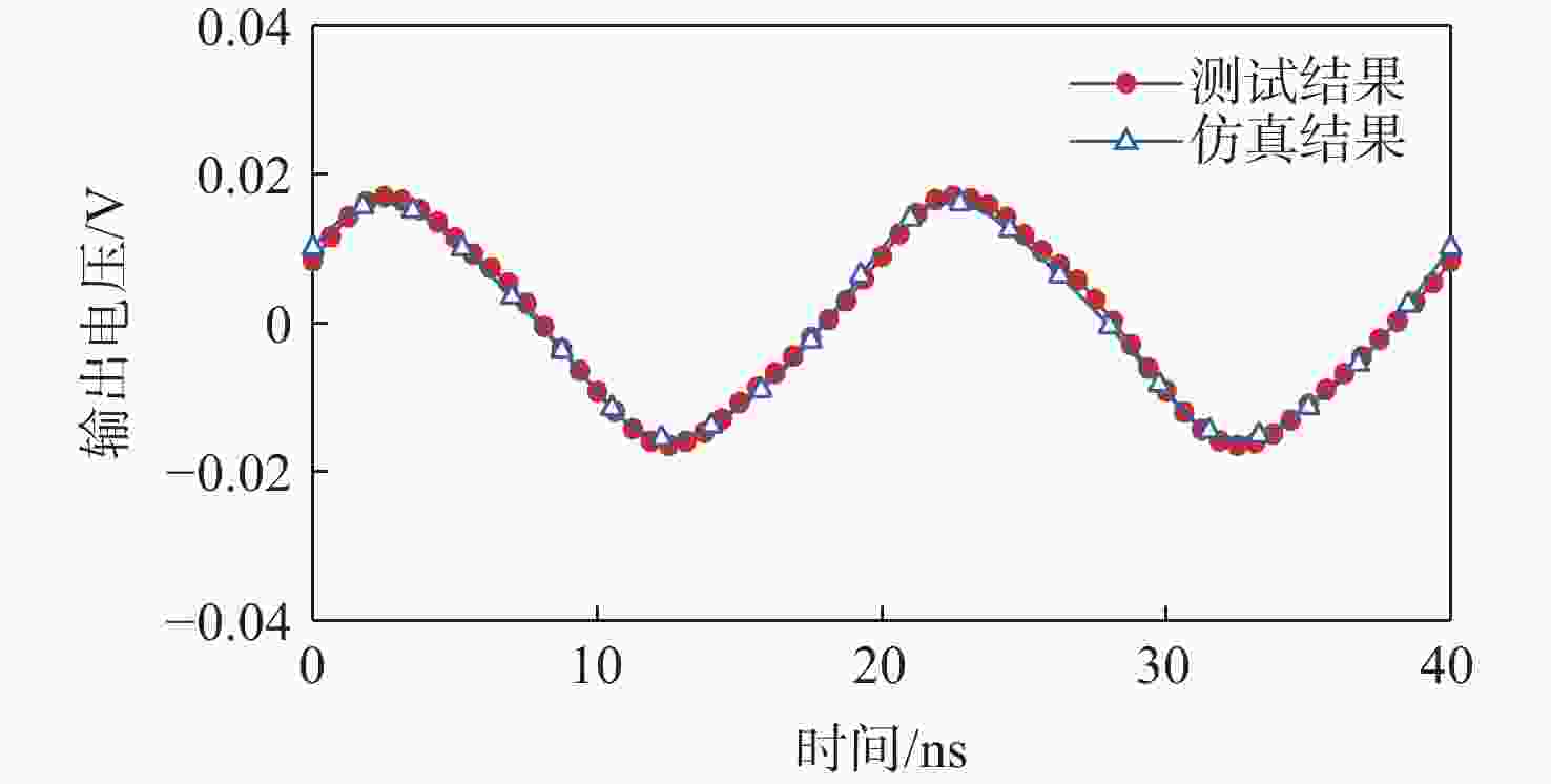
图 24 f=50 MHz,PF=5 dBm时,测试结果和仿真结果的对比
Figure 24. Comparison of test and simulation results at f=50 MHz, PF=5 dBm
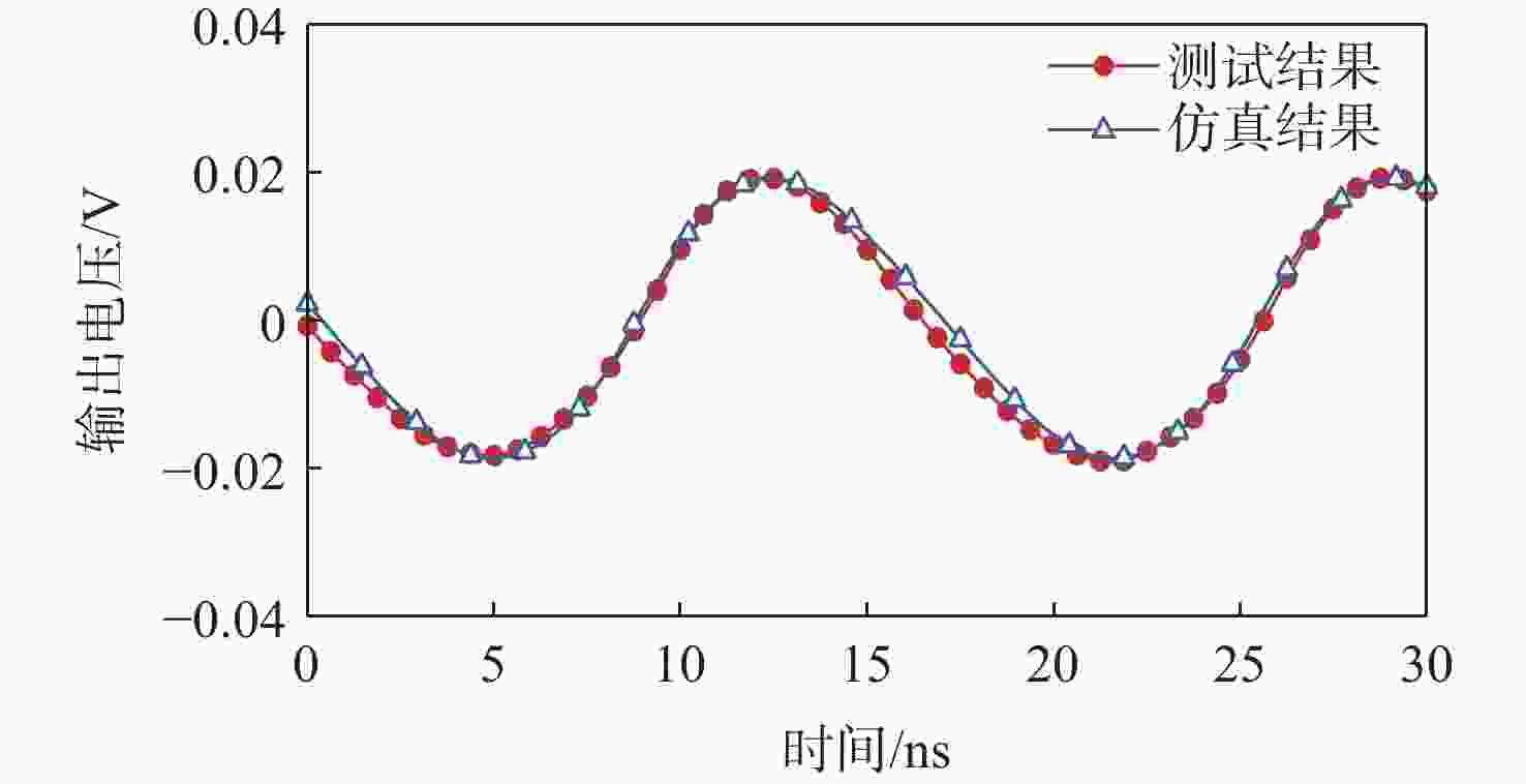
图 25 f=60 MHz,PF=5 dBm时,测试结果和仿真结果的对比
Figure 25. Comparison of test and simulation results at f=60 MHz, PF=5 dBm
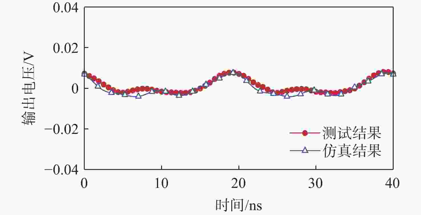
图 26 f=50 MHz,PF=10 dBm时测试结果和仿真结果的对比
Figure 26. Comparison of test and simulation results at f=50 MHz, PF=10 dBm
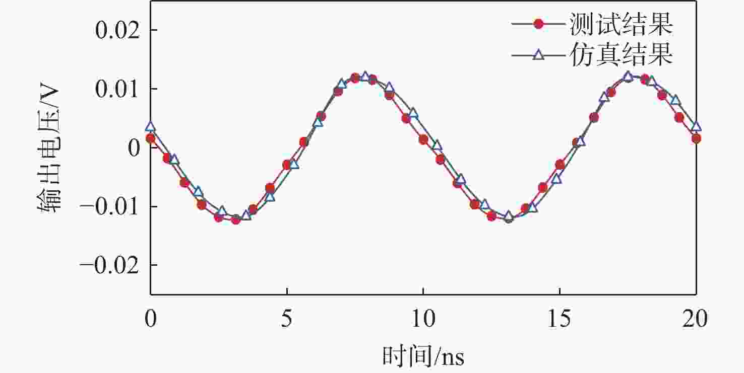
图 27 f=100 MHz,PF=10 dBm时,测试结果和仿真结果的对比
Figure 27. Comparison of test and simulation results at f=100 MHz, PF=10 dBm
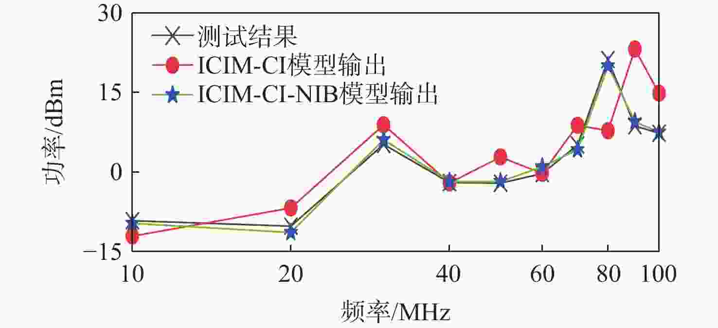
图 28 2种建模方法的敏感性预测与DPI测量结果的比较对比
Figure 28. Comparative comparison of immunity prediction and DPI measurements for the two modeling approaches
表 1 干扰后的运算放大器的输出类型和描述
Table 1. Output types and descriptions of operational amplifier after interference
 下载: 导出CSV
表 2 不同干扰频率和功率下模型仿真结果和测试数据的NMSE
Table 2. NMSE of model simulation results and test data at different interference frequencies and powers
干扰注入频率/MHz 干扰注入功率PF/dBm NMSE/dB 10 0 − 27.4876 40 −5 − 36.8490 50 −5 − 28.6725 50 0 − 34.2422 50 5 − 30.9985 50 10 − 19.8894 60 5 − 28.9814 100 10 − 25.8291
下载: 导出CSV
表 3 2种模型归一化均方根误差和建模时间等信息对比
Table 3. Comparison of information such as normalized root mean square error and modeling time for two models
信号类型 建模方法 NMSE 建模时间/s 是否可以开展级
联量化仿真时域 ICIM-CI-NIB − 30.9200 21.0 是 ICIM-CI 否 频域 ICIM-CI-NIB − 31.3352 34.8 是 ICIM-CI − 12.7982 498.0 否
下载: 导出CSV
-
[1] MASETTI G, GRAFFI S, GOLZIO D, et al. Failures induced on analog integrated circuits by conveyed electromagnetic interferences: a review[J]. Microelectronics Reliability, 1996, 36(7-8): 955-972. [2] LOECKX J, GIELEN G. Assessment of the DPI standard for immunity simulation of integrated circuits[C]//Proceedings of the IEEE International Symposium on Electromagnetic Compatibility. Piscataway: IEEE Press, 2007: 1-5. [3] International Electrotechnical Commission. Integrated circuits-measurement of electromagnetic immunity 150 kHz to 1 GHz-Part 4: direct RF power injection method: IEC 62132-4: 2006[S]. Geneva : International Electrotechnical Commission, 2006. [4] GAZDA C, GINSTE D V, ROGIER H, et al. An immunity modeling technique to predict the influence of continuous wave and amplitude modulated noise on nonlinear analog circuits[C]//Proceedings of the International Symposium on Electromagnetic Compatibility. Piscataway: IEEE Press, 2013. [5] CHAHINE I, KADI M, GABORIAUD E, et al. Characterization and modeling of the susceptibility of integrated circuits to conducted electromagnetic disturbances up to 1 GHz[J].IEEE Transactions on Electromagnetic Compatibility, 2008, 50(2): 285-293. [6] CEPERIC V, BARIC A. Modelling of electromagnetic immunity of integrated circuits by artificial neural networks[C]//Proceedings of the 20th International Zurich Symposium on Electromagnetic Compatibility. Piscataway: IEEE Press, 2009: 373-376. [7] SCHROTER M, PEHLKE D R, LEE T Y. Compact modeling of high-frequency distortion in silicon integrated bipolar transistors[J]. IEEE Transactions on Electron Devices, 2000, 47(7): 1529-1535. [8] WANG H D, JNGFU B, WU Z D. Multislice behavioral modeling based on envelope domain for power amplifiers[J]. Journal of Systems Engineering and Electronics, 2009, 20(2): 274-277. [9] NGOYA E, QUINDROIT C, NEBUS J M. On the continuous-time model for nonlinear-memory modeling of RF power amplifiers[J]. IEEE Transactions on Microwave Theory and Techniques, 2009, 57(12): 3278-3292. [10] LAFON F, RAMDANI M, PERDRIAU R, et al. An industry-compliant immunity modeling technique for integrated circuits[C]//Proceedings of the International Symposium on Electromagnetic Compatibility. Piscataway: IEEE Press, 2009. [11] International Electrotechnical Commission. Integrated circuit EMC IC modeling-Part 4: ICIM-CI, integrated circuit immunity model, conducted immunity: IEC 62433-4: 2016[S]. Geneva: International Electrotechnical Commission, 2016. [12] KHAN Q M, KOOHESTANI M, LEVANT J L, et al. Validation of IC conducted emission and immunity models including aging and thermal stress[J]. IEEE Transactions on Electromagnetic Compatibility, 2023, 65(3): 780-793. [13] BOYER A, SICARD E. A case study to apprehend RF susceptibility of operational amplifiers[C]//Proceedings of the 12th International Workshop on the Electromagnetic Compatibility of Integrated Circuits. Piscataway: IEEE Press, 2019: 13-15. [14] LAFON F, DE DARAN F, RAMDANI M, et al. Immunity modeling of integrated circuits: an industrial case[J]. IEICE Transactions on Communications, 2010, E93. B(7): 1723-1730. [15] WANG Z Y, ZHOU C L, LIU T, et al. Nonlinear behavior immunity modeling of an LDO voltage regulator under conducted EMI[J].IEEE Transactions on Electromagnetic Compatibility, 2016, 58(4): 1016-1024. [16] VERSPECHT J, ROOT D E, WOOD J, et al. Broad-band, multi-harmonic frequency domain behavioral models from automated large-signal vectorial network measurements[C]//Proceedings of the IEEE MTT-S International Microwave Symposium Digest. Piscataway: IEEE Press, 2005: 1975-1978. [17] ROOT D E, VERSPECHT J, SHARRIT D, et al. Broad-band poly-harmonic distortion (PHD) behavioral models from fast automated simulations and large-signal vectorial network measurements[J]. IEEE Transactions on Microwave Theory and Techniques, 2005, 53(11): 3656-3664. [18] VERSPECHT, ROOT D E. Polyharmonic distortion modeling[J]. IEEE Microwave Magazine, 2006, 7(3): 44-57. [19] International Electrotechnical Commission. Integrated circuits—Measurement of electromagnetic immunity 150 kHz to 1 GHz-Part 1: General conditions and definitions: IEC 62132-1: 2015[S]. Geneva: International Electrotechnical Commission, 2015. [20] RICHELLI A. EMI susceptibility issue in analog front-end for sensor applications[J]. Journal of Sensors, 2016, 2016: 1082454. [21] POULTON A S. Effect of conducted EMI on the DC performance of operational amplifiers[J]. Electronics Letters, 1994, 30(4): 282-284. [22] SETTI G, SPECIALE N. Design of a low EMI susceptibility CMOS transimpedance operational amplifier[J].Microelectronics Reliability, 1998, 38(6-8): 1143-1148. [23] Keysight Technologies, Inc. NVNA help-general hardware configuration: E5080A-90001[R]. Santa Rosa: Keysight Technologies, 2023: 1-8. -

 下载:
下载:


 点击查看大图

计量
- 文章访问数: 376
- HTML全文浏览量: 187
- PDF下载量: 61
- 被引次数: 0
