


-
摘要:
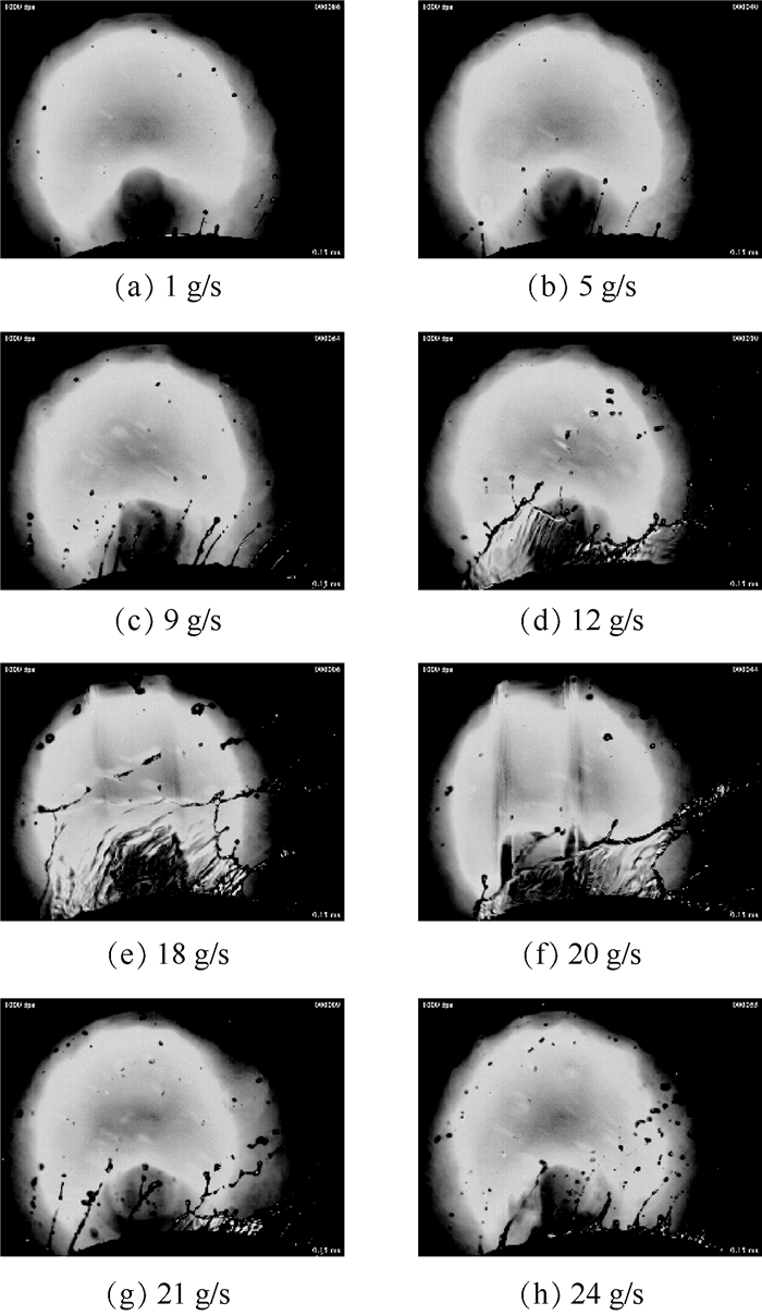
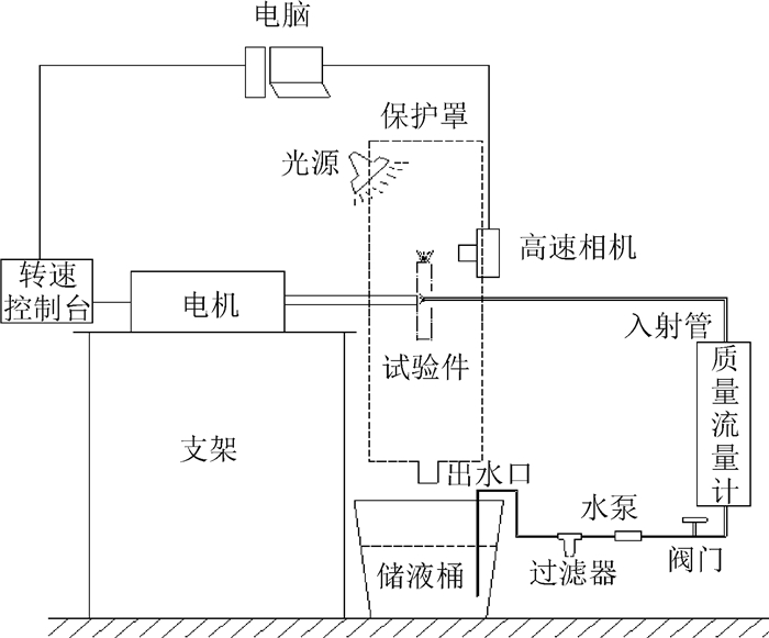
为了解重力对旋转圆盘表面液体流动的影响,利用高速摄影,对垂直旋转圆盘边缘液体形态进行了试验研究。结果表明,与水平旋转圆盘边缘液体分为直接液滴、液柱和液膜3种形态不同,垂直旋转圆盘边缘液体分为液柱、液膜和柱膜纠缠3种形态。垂直旋转圆盘底部与顶部液体形态并不一致。底部未出现液膜形态,当流量不大于24 g/s时,为液柱形态;当流量大于等于30 g/s时,为柱膜纠缠形态。当流量为12~21 g/s、转速为1 000~2 100 r/min,顶部出现液膜形态;当流量小于12 g/s时,顶部为液柱形态;当流量大于12 g/s时,液柱形态消失,由柱膜纠缠形态取代。由于重力影响,垂直旋转圆盘边缘液体形态变化程度远大于水平旋转圆盘;在流量大到一定程度后,圆盘底部形成液柱形态需要的转速会大大增加。
Abstract:For finding how the gravity affects the liquid on the rotating disc, the liquid morphology at the edge of the vertical rotating disc was experimentally studied by high-speed photography. The results show that there are three liquid morphologies at the edge of the vertical rotating disc:column, film and column film entanglement, which is different with the three morphologies at the horizontal rotating disc edge:direct drop, column and film. The liquid morphology at the bottom of the vertical disc does not match the top one, and the film morphology does not occur at the bottom. When the mass flow rate is less than 24 g/s, the liquid shows column morphology at the bottom, and when the mass flow rate is greater than or equal to 30 g/s, the liquid shows column film entanglement morphology. When the mass flow rate is between 12 g/s and 21 g/s and the rotating speed is between 1 000 r/min and 2 100 r/min, the liquid film morphology appears at the top of the disc. The liquid morphology is column when the mass flow rate is less than 12 g/s; if the mass flow rate is greater than 12 g/s, it will be replaced by column film entanglement. Due to the influence of gravity, the liquid morphology at the vertical disc edge changes much more than the horizontal disc; when the mass flow rate is large enough, the rotating speed required to form the liquid column at the bottom of the disc is greatly increased.
-
Key words:
- rotating atomizer /
- vertical rotating disc /
- liquid morphology /
- high-speed photography /
- atomization
-

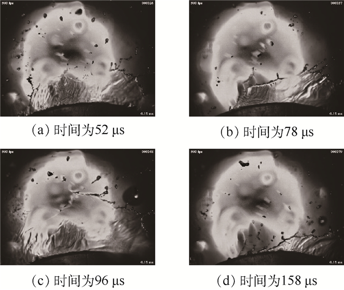
图 4 不同转速下圆盘底部液体形态
Figure 4. Liquid morphology of disc bottom at different rotating speeds

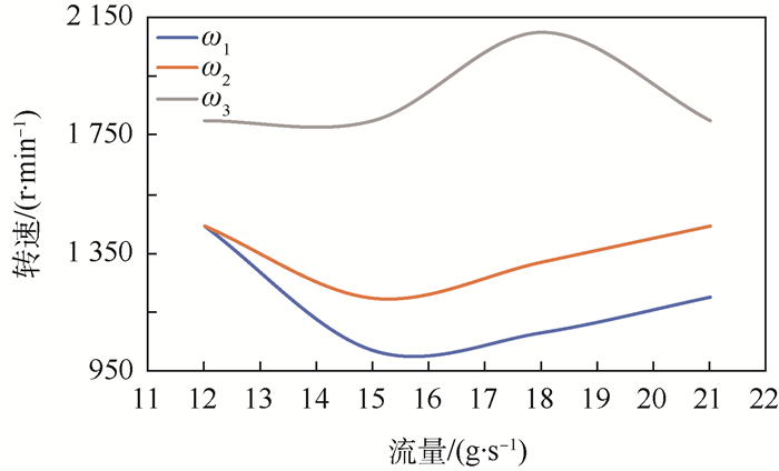
图 9 液膜存在时转速-流量关系
Figure 9. Relation between rotating speed and flow rate when liquid film exists
-
[1] GIANFRANCESCO A, TURCHIULI C, FLICK D, et al.CFD modeling and simulation of maltodextrin solutions spray drying to control stickiness[J].Food and Bioprocess Technology, 2010, 3(6):946-955. doi: 10.1007/s11947-010-0352-2 [2] LI X H, ZONG L W, JIN X T.Recent progress of spray drying in China[J].Drying Technology, 1999, 17(9):1747-1757. [3] JIN Y, CHEN X D.A three-dimensional numerical study of the gas/particle interactions in an industrial-scale spray dryer for milk powder production[J].Drying Technology, 2009, 27(10):1018-1027. doi: 10.1080/07373930903203588 [4] SENUMA Y, HILBORN J G.High speed imaging of drop formation from low viscosity liquids and polymer melts in spinning disk atomization[J].Polymer Engineering and Science, 2002, 42(5):969-982. doi: 10.1002/(ISSN)1548-2634 [5] SOMA T, KATAYAMA T, TANIMOTO J, et al.Liquid film flow on a high speed rotary bell-cup atomizer[J].International Journal of Multiphase Flow, 2015, 70:96-103. doi: 10.1016/j.ijmultiphaseflow.2014.11.013 [6] ELLWOOD K R J, TARDIFF J L, ALAIE S M.A simplified analysis method for correlating rotary atomizer performance on droplet size and coating appearance[J].Journal of Coatings Technology and Research, 2014, 11(3):303-309. doi: 10.1007/s11998-013-9535-x [7] COLBERT S A, CAIRNCROSS R A.A discrete droplet transport model for predicting spray coating patterns of an electrostatic rotary atomizer[J].Journal of Electrostatics, 2006, 64(3-4):234-246. doi: 10.1016/j.elstat.2005.06.003 [8] DOMNICK J, SCHEIBE A, YE Q.The simulation of the electrostatic spray painting process with high-speed rotary bell atomizers.Part Ⅰ:Direct charging[J].Particle & Particle Systems Characterization, 2005, 22(2):141-150. https://www.mendeley.com/catalogue/simulation-electrostatic-spray-painting-process-highspeed-rotary-bell-atomizers-part-i-direct-chargi/ [9] DOMNICK J, SCHEIBE A, YE Q.The simulation of electrostatic spray painting process with high-speed rotary bell atomizers.Part Ⅱ:External charging[J].Particle & Particle Systems Characterization, 2006, 23(5):408-416. http://www.deepdyve.com/lp/wiley/the-simulation-of-electrostatic-spray-painting-process-with-high-speed-sDSb1vXY7I [10] WANG D, LING X, PENG H.Simulation of ligament mode breakup of molten slag by spinning disk in the dry granulation process[J].Applied Thermal Engineering, 2015, 84:437-447. doi: 10.1016/j.applthermaleng.2015.03.003 [11] WANG D, PENG H, LING X.Ligament mode disintegration of liquid film at the rotary disk rim in waste heat recovery process of molten slag[J].Energy Procedia, 2014, 61:1824-1829. doi: 10.1016/j.egypro.2014.12.222 [12] LIU J, YU Q, LI P, et al.Cold experiments on ligament formation for blast furnace slag granulation[J].Applied Thermal Engineering, 2012, 40:351-357. doi: 10.1016/j.applthermaleng.2012.01.063 [13] MIZUOCHI T, AKIYAMA T, SHIMADA T, et al.Feasibility of rotary cup atomizer for slag granulation[J].ISIJ International, 2001, 41(12):1423-1428. doi: 10.2355/isijinternational.41.1423 [14] ZHANG H, WANG H, ZHU X, et al.A review of waste heat recovery technologies towards molten slag in steel industry[J].Applied Energy, 2013, 112:956-966. doi: 10.1016/j.apenergy.2013.02.019 [15] MORISHITA T.A development of the fuel atomizing device utilizing high rotational speed: ASME 81-GT-180[R].New York: ASME, 1981. [16] CHOI S M, JANG S H.Spray behavior of the rotary atomizer with in-line injection orifices[J].Atomization and Sprays, 2010, 20(10):863-875. doi: 10.1615/AtomizSpr.v20.i10 [17] DAHM W J A, PATEL P R, LERG B H.Experimental visualizations of liquid breakup regimes in fuel slinger atomization[J].Atomization and Sprays, 2006, 16(8):933-944. doi: 10.1615/AtomizSpr.v16.i8 [18] WERNER D.Fundamental analysis of liquid atomization by fuel slingers in small gas turbines: AIAA-2002-3183[R].Reston: AIAA, 2002. [19] TESKE M E, THISTLE H W, HEWITT A J, et al.Rotary atomizer drop size distribution database[J].Transactions of the ASABE, 2005, 48(3):917-921. doi: 10.13031/2013.18496 [20] BAGHERPOUR A, MCLEOD I M, HOLLOWAY A G L.Droplet sizing and velocimetry in the wake of rotary-cage atomizers[J].Transactions of the ASABE, 2012, 55(3):759-772. doi: 10.13031/2013.41508 [21] CRAIG I P, HEWITT A, TERRY H.Rotary atomiser design requirements for optimum pesticide application efficiency[J].Crop Protection, 2014, 66:34-39. doi: 10.1016/j.cropro.2014.08.012 [22] GEBHARDT M R.Rotary disk atomization[J].Weed Technology, 1988, 1(2):106-113. http://d.old.wanfangdata.com.cn/NSTLQK/NSTL_QKJJ023727449/ [23] MATSUMOTO S, SAITO K, TAKASHIMA Y.Phenomenal transition of liquid atomization from disk[J].Journal of Chemical Engineering of Japan, 1974, 7(1):13-19. doi: 10.1252-jcej.16.338/ [24] TEUNOU E, PONCELET D.Rotary disc atomisation for microencapsulation applications-Prediction of the particle trajectories[J].Journal of Food Engineering, 2005, 71(4):345-353. https://www.sciencedirect.com/science/article/abs/pii/S0260877404005370 [25] LIU J, YU Q, GUO Q.Experimental Investigation of liquid disintegration by rotary cups[J].Chemical Engineering Science, 2012, 73:44-50. doi: 10.1016/j.ces.2012.01.010 [26] AHMED M, YOUSSEF M S.Influence of spinning cup and disk atomizer configurations on droplet size and velocity characteristics[J].Chemical Engineering Science, 2014, 107:149-157. doi: 10.1016/j.ces.2013.12.004 [27] WANG D, LING X, PENG H, et al.Experimental investigation of ligament formation dynamics of thin viscous liquid film at spinning disk edge[J].Industrial & Engineering Chemistry Research, 2016, 34(55):9267-9275. https://www.onacademic.com/detail/journal_1000039550307710_b5da.html [28] FROST A R.Rotary atomization in the ligament formation mode[J].Journal of Agricultural Engineering Research, 1981, 26(1):63-78. doi: 10.1016/0021-8634(81)90127-X [29] HINZE J O, MILBORN H.Atomization of liquids by means of a rotating cup[J].Journal of Applied Mechanics-Transactions of the ASME, 1950, 17(2):145-153. -

 下载:
下载:


 点击查看大图
计量
- 文章访问数: 614
- HTML全文浏览量: 99
- PDF下载量: 308
- 被引次数: 0
