


Comparative experimental study on wind tunnel based on WDPR-8 and machetes tail support
-
摘要:
对国内近年设计的具有典型先进战斗机布局的动态试验标模,采用8绳牵引的绳牵引并联机器人(WDPR-8)支撑和传统弯刀尾支撑在FL-5风洞中进行对比吹风试验。根据风洞试验环境及仿真计算系统的刚度与工作空间,设计了满足要求的WDPR-8绳系结构和支撑机构,并建造了样机;在阻塞比及两心距足够小的前提下,保证了模型在两支撑系统中的通用性,以此设计内置六分量杆式天平的试验模型;利用绳拉力信号并联WDPR-8视觉采集系统与风洞VSS采集系统,实现气动力、机器视觉和绳拉力3个采集系统同步工作;在除支撑系统以外其他试验条件保持一致的条件下,进行重复性试验、纵向试验和横向试验。数据处理时,弯刀尾支撑进行了尾支架修正,WDPR-8支撑未修正。比较对照试验结果可得:两者在纵向试验的重复性试验所得升力系数最大均方差差别很小,2种支撑得到的升力系数、阻力系数和俯仰力矩系数的最大均方差不超过3.6%;横向试验在试验攻角范围内,2种支撑得到的侧向力系数对侧滑角的导数变化规律基本相同。用WDPR-8支撑进行的单自由度俯仰振荡试验得到的升力系数迟滞环曲线各环首尾连续,与静态升力系数曲线走势一致,且非定常迟滞环面积随减缩频率增大而增大,符合物理意义。试验研究结果反映出WDPR-8支撑的可行性及结果的有效性。
-
关键词:
- 风洞试验 /
- 对比试验 /
- 绳牵引并联机器人(WDPR) /
- 弯刀尾支撑 /
- 气动特性
Abstract:For a dynamic test model designed in China in recent years with a typical advanced fighter layout, Wire-Driven Parallel Robot with 8 Wires (WDPR-8) support and a traditional machetes tail support were used in a FL-5 wind tunnel for a comparative blow test. According to the wind tunnel test environment and the system's stiffness and working space, WDPR-8 wire structure and supporting mechanism were designed, and the prototype was built; for the blocking ratio and the distance between the two centers are small, the versatility of the model in the two support systems was ensured, and the test model of the built-in six-component bar balance was designed; the wire tension signal is used to parallel the WDPR-8 vision acquisition system and the wind tunnel VSS acquisition system to achieve that the three systems work synchronously. Repeatable tests, longitudinal tests, and transverse tests were performed under conditions in which the test conditions are consistent except for the support system. During data processing, the WDPR-8 was not modified for the tail bracket, and the tail support was modified for the tail bracket. The comparison of the test results of the two supports shows that the maximum mean square error of the lift coefficient obtained by the repeated tests in longitudinal test is near. The maximum mean square error of lift coefficient, drag coefficient, pitching moment coefficient obtained by the two supports do not exceed 3.6%. In the transverse test, the variation law of the derivative of the lateral force coefficient to the side slip angle obtained by the two supports are basically the same throughout the test angle of attack. The lift coefficient hysteresis loop curve obtained from the single-degree-of-freedom pitch oscillation test performed with WDPR-8 is consistent with the static lift coefficient curve. The lift coefficient hysteresis loop was continuous from beginning to end, and the area of the unsteady hysteresis loop increases with the shrinkage frequency, which is in line with the physical meaning. The experimental research results reflect the feasibility and effectiveness of the WDPR-8 support.
-

图 3 WDPR-8支撑原理样机结构示意图
Figure 3. Schematic diagram of structure of WDPR-8 support prototype

图 5 WDPR-8支撑机构运动学关系示意图
Figure 5. Schematic diagram of WDPR-8 support institutional kinematics relationship

图 7 应用于弯刀尾支撑下的模型结构剖面图
Figure 7. Model structure profile applied to mathetes tail support
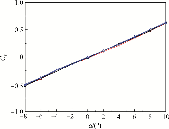
图 9 基于WDPR-8支撑试验结果精度验证
Figure 9. Accuracy verification based on WDPR-8 support test results

图 10 升力特性曲线对比(V0=30 m/s)
Figure 10. Comparison of lift characteristic curves atV0=30 m/s
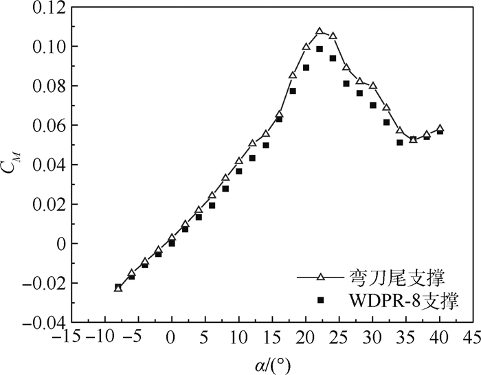
图 12 俯仰力矩系数曲线对比(V0=30 m/s)
Figure 12. Comparison of pitching moment coefficient curves at V0=30 m/s
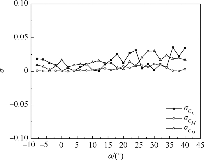
图 13 两种支撑结果气动系数的均方根误差曲线(V0=30 m/s)
Figure 13. Mean square error curves of aerodynamic coefficients of two kinds of support results at V0=30 m/s

图 14 纵向静稳定度对比(V0=30 m/s)
Figure 14. Comparison of longitudinal static stabilityat V0=30 m/s
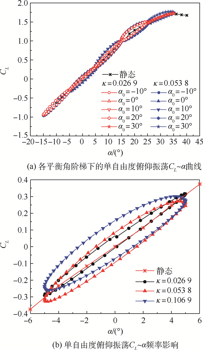
图 16 单自由度俯仰振荡升力系数曲线
Figure 16. Single-degree-of-freedom pitching oscillation lift coefficient curves
表 1 WDPR-8支撑的结构参数
Table 1. Table 1 Structure parameter of WDPR-8 support
i Pi/mm Bi/mm xb yb zb xg yg zg 1 -332 125 -4 240 733 -1 910 2 -332 -125 -4 240 -733 -1 910 3 0 -642 -13 -443 -599 -1 910 4 0 642 -13 -443 599 -1 910 5 0 61 14 -347 346 -70 6 -332 125 4 77 588 -70 7 -332 -125 4 77 -588 -70 8 0 -61 14 -347 -346 -70  下载: 导出CSV
表 2 风洞试验工况
Table 2. State and condition of wind tunnel test
参数 数值 风速V0/(m·s-1) 20, 30 攻角/(°) -8~40 侧滑角/(°) 0, -5, -10, -15 室温/℃ 15 模型 动态试验标模
下载: 导出CSV
表 3 重复性试验的均方差结果
Table 3. Mean variance results of repeatability tests
α/(°) 均方差/% WDPR-8支撑 弯刀尾支撑 -8 1.048 0.685 -6 1.125 0.742 -4 0.972 0.798 -2 0.741 0.674 0 1.077 0.847 2 1.072 0.831 4 1.350 0.917 6 1.116 0.771 8 1.050 0.760 10 1.070 1.156
下载: 导出CSV
表 4 两种支撑所得侧向力系数的最大均方根误差
Table 4. Maximum mean square error of lateral force coefficient obtained from two supports
α/(°) σCYmax/% β=0° β=-5° β=-10° β=-15° -8~10 0.521 0.655 0.828 1.396 -8~12 0.786 0.788 0.828 1.396 -8~40 5.286 3.755 5.353 10.627
下载: 导出CSV
-
[1] TUTTLE M H.Support interference of wind tunnel models: A selective annotated bibliography[R].Washington, D.C.: NASA Langley Research Center, 1981. [2] 李周复.风洞试验手册[M].北京:航空工业出版社, 2015:140.LI Z F.Wind tunnel test manual[M].Beijing:Aviation Industry Press, 2015:140(in Chinese). [3] 王勋年, 孙正荣.低速风洞试验[M].北京:国防工业出版社, 2002:326.WANG X N, SUN Z R.Low speed wind tunnel test[M].Beijing:National Defense Industry Press, 2002:326(in Chinese). [4] XIAO Y W, LIN Q, ZHENG Y Q, et al.Model aerodynamic tests with a wire-driven parallel suspension system in low-speed wind tunnel[J].Chinese Journal of Aeronautics, 2010, 23(4):393-400. doi: 10.1016/S1000-9361(09)60233-8 [5] 王晓光, 林麒.风洞试验绳牵引并联支撑技术研究进展[J].航空学报, 2018, 39(10):122064.WANG X G, LIN Q.Progress in wire-driven parallel suspension technologies in wind tunnel tests[J].Acta Aeronautica et Astronautica Sinica, 2018, 39(10):122064(in Chinese). [6] LAMBERT T J, VUKASINOVIC B, GLEZER A.A six degrees of freedom dynamic wire-driven traverse[J].Aerospace, 2016, 3(2):11. doi: 10.3390/aerospace3020011 [7] LAMBERT T J, VUKASINOVIC B, GLEZER A.Aerodynamic flow control of wake dynamics coupled to a moving bluff body: AIAA 2016-4081[R].Reston: AIAA, 2016. [8] STURM C, LALO W, BRUCKMANN T.Wire robot suspension systems for wind tunnels[J].Wind Tunnels and Experimental Fluid Dynamics Research, 2011, 7(27):709. [9] LAFOURCASE P, LLIBRE M, REBOULET C.Design of a parallel wire-driven manipulator for wind tunnels[C]//Proceedings of the Workshop on Fundamental Issues and Future Research Directions for Parallel Mechanisms and Manipulators, 2002: 187-194. [10] LAFOURCASE P, LLIBRE M, REBOULET C.First steps toward a sketch-based design methodology for wire-driven manipulators[C]//IEEE/ASME International Conference on Advanced Intelligent Mechatronics.Piscataway: IEEE Press, 2003: 143-148. [11] LAFOURCASE P.Study of parallel manipulators with cables, design of an active suspension for wind tunnel[D].Paris: ENSAE, 2004: 22-29. [12] GRIFFIN S A, CROOKS R S, MOLE P J.Vane support system (VSS)-A new generation wind tunnel model support system: AIAA-91-0398[R].Reston: AIAA, 1991. [13] 冀洋锋, 林麒, 胡正红, 等.基于绳系并联机器人支撑系统的SDM动导数试验可行性研究[J].航空学报, 2017, 38(11):121330.JI Y F, LIN Q, HU Z H, et al.Research on feasibility of dynamic stability derivatives test of SDM with wire-driven parallel robot suspension system[J].Acta Aeronautica et Astronautica Sinica, 2017, 38(11):121330(in Chinese). [14] 林麒, 冀洋锋.一种可实现风洞虚拟飞行的模型绳索支撑系统: CN104132795A[P].2014-11-05.LIN Q, JI Y F.Model rope support system capable of realizing virtual flight of wind tunnel: CN104132795A[P].2014-11-05(in Chinese). [15] 国防科学技术工业委员会.高速风洞和低速风洞测力实验精度指标: GJB 1061-91[S].北京: 国防科学技术工业委员会, 1991.National Defense Science, Technology and Industry Commission.Requirement for force-Test precision of high and low speed wind tunnels: GJB 1061-91[S].Beijing: National Defense Science, Technology and Industry Commission, 1991(in Chinese). [16] 郝卫东, 司永昌, 高静.民机低速风洞测力试验技术研究[J].流体力学实验与测量, 2004, 18(4):34-37. doi: 10.3969/j.issn.1672-9897.2004.04.008HAO W D, SI Y C, GAO J.Investigation of civil airplane force measurement in low speed wind tunnel[J].Fluid Mechanics Experiment and Measurement, 2004, 18(4):34-37(in Chinese). doi: 10.3969/j.issn.1672-9897.2004.04.008 [17] 王勋年, 祝明红, 孙传宝.低速大迎角尾撑支架干扰试验研究[J].实验流体力学, 2007, 21(2):8-12. doi: 10.3969/j.issn.1672-9897.2007.02.002WANG X N, ZHU M H, SUN C B.Investigation on the interference of rear sting supports at high angle of attack in low speed wind-tunnel[J].Journal of Experiments in Fluid Mechanics, 2007, 21(2):8-12(in Chinese). doi: 10.3969/j.issn.1672-9897.2007.02.002 [18] 殷春平, 陈艺峰, 吴了泥, 等.基于粒子群算法的摄像机标定过程优化[J].机电工程, 2012, 29(1):100-103.YIN C P, CHEN Y F, WU L N, et al.Optimization of camera calibration process based on PSO algorithm[J].Mechanical & Electrical Engineering Magazine, 2012, 29(1):100-103(in Chinese). [19] 陈艺峰.悬挂式飞行器模型姿态的单目视觉测量方法研究[D].厦门: 厦门大学, 2012: 74.CHEN Y F.Research on monocular vision measurement method for model attitude of suspended aircraft[D].Xiamen: Xiamen University, 2012: 74(in Chinese). [20] 赵小见, 赵磊, 冯峰, 等.某空腔低速流动噪声风洞试验[J].航空学报, 2015, 36(7):2145-2154.ZHAO X J, ZHAO L, FENG F, et al.Wind tunnel test into noise induced by low-speed cavity flow[J].Acta Aeronautica et Astronautica Sinica, 2015, 36(7):2145-2154(in Chinese). [21] 李国帅, 魏志, 李巍, 等.现代试验设计方法在高速风洞试验中的应用[J].航空学报, 2015, 36(3):782-788.LI G S, WEI Z, LI W, et al.Using modern design of experiments methodologies for high speed wind tunnel tests[J].Acta Aeronautica et Astronautica Sinica, 2015, 36(3):782-788(in Chinese). [22] 刘大伟, 熊贵天, 刘洋, 等.宽体客机高速风洞试验数据修正方法[J].航空学报, 2019, 40(2):522205.LIU D W, XIONG G T, LIU Y, et al.Method of test data correction for wide-body aircraft in high speed wind tunnel[J].Acta Aeronautica et Astronautica Sinica, 2019, 40(2):522205(in Chinese). -

 下载:
下载:


 点击查看大图

计量
- 文章访问数: 683
- HTML全文浏览量: 128
- PDF下载量: 231
- 被引次数: 0
