


-
摘要:
自动铺丝是一种先进的复合材料自动制造技术,广泛应用于制造形面复杂的复合材料构件。大曲率区域丝束的压实质量较差、铺放路径的方向偏差和转弯半径难以同时满足等问题,导致了各种铺放缺陷。研究了曲面曲率对路径性能的影响,建立了分区域路径规划机制。采用压辊到曲面的距离来表征丝束压实情况,并根据曲面曲率估算可压实丝束的数量。建立了局部方向偏差和转弯半径计算方法,并在路径密化过程中实时评价,在路径性能超出约束时进行分区。考虑了丝束压实、方向偏差及转弯半径对铺放路径的约束,保证了整张曲面的铺放质量和铺放效率。在翼梢小翼曲面上完成了路径规划方法的仿真和实验验证,结果表明:所提方法能够在复杂曲面上获得满足性能要求的铺放路径。
Abstract:Automated fiber placement is an advanced automatic manufacturing technology for composite materials, which is widely used in manufacturing composite components with complex shapes. However, the compaction quality of the fiber in the area of large curvature is poor. In addition, it is difficult to satisfy the directional deviation and the turning radius of the placement path at the same time, resulting in various placement defects. In this paper, the influence of surface curvature on path performance is studied and a new path planning method for complex surfaces with area partition is established. The distance between roller and the mold surface is used to estimate the fiber compaction quality and the fiber number placed simultaneously can be calculated by the surface curvature. The local direction deviation and steering radius are evaluated during the path generation process, and a new sector is partitioned when the evaluation results are out of constraints. The method fully considers the influence of compaction quality, direction deviation and turning radius on paving path, so that the placement quality and efficiency of the entire curved surface can be ensured. Simulations and experiments are completed on the winglet surface to verify the path planning method, and the results show that, by the proposed method, satisfactory component placement quality can be obtained on complex surface.
-

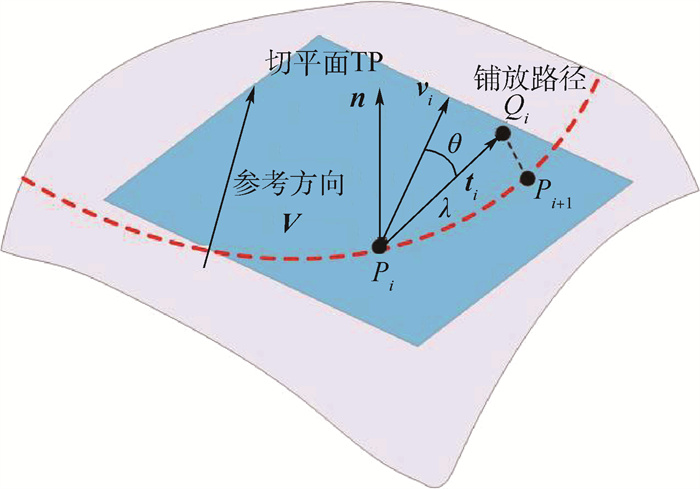
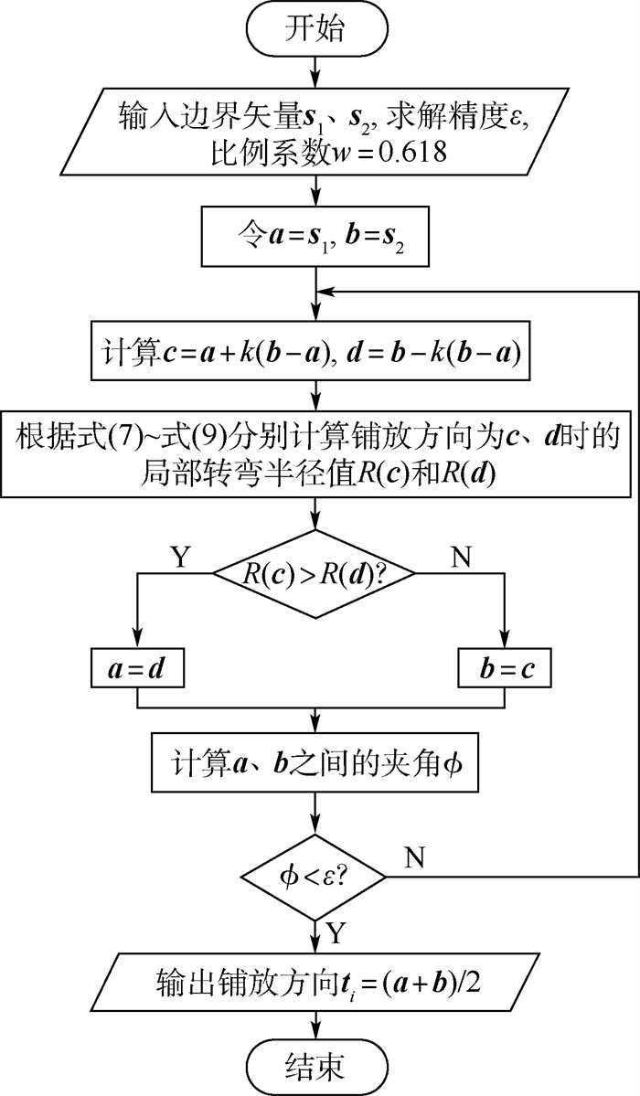
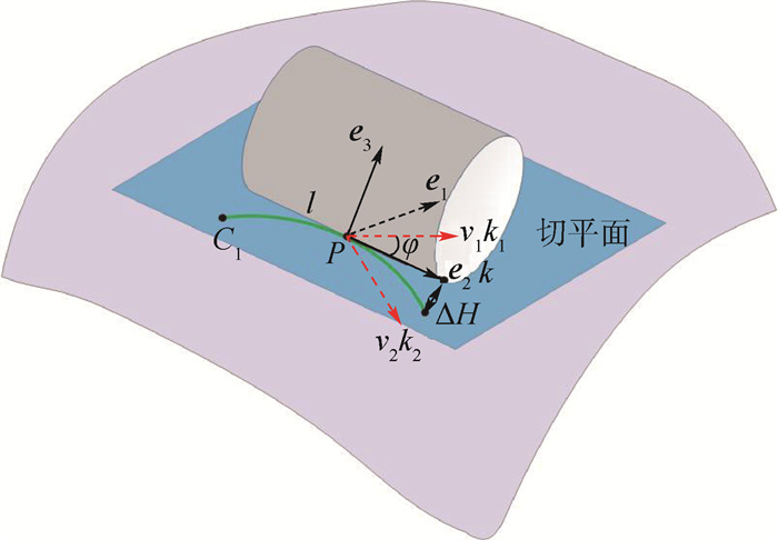
图 5 黄金分割法优化局部铺放方向
Figure 5. Optimization of local paving direction using golden section method

图 7 翼梢小翼曲面上的可铺放丝束数量分布
Figure 7. Distribution of the number of tows that can be paved on winglet surface
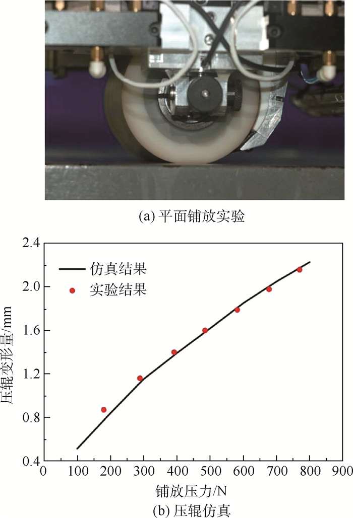
表 1 压辊模型的主要参数
Table 1. Main parameters of pressure roller model
参数 压辊内径/mm 压辊外径/mm 压辊长度/mm 压辊轴弹性模量/MPa 压辊轴泊松比 模具弹性模量/MPa 模具泊松比 数值 40 85 130 210 000 0.3 210 000 0.3  下载: 导出CSV
表 2 方向偏差、转弯半径和压实情况
Table 2. Direction deviation, turning radius and compaction
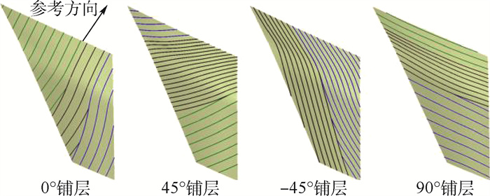
铺层角度/(°) 方向偏差/(°) 转弯半径/mm 压实距离/mm 0 9.8 1 557.4 1.2 45 9.6 1 530.9 1.3 -45 8.5 1 975.0 0.9 90 9.7 1 552.6 1.5
下载: 导出CSV
-
[1] BEAKOU A, CANO M, LE J B, et al. Modelling slit tape buckling during automated prepreg manufacturing: A local approach[J]. Composite Structures, 2011, 93(10): 2628-2635. doi: 10.1016/j.compstruct.2011.04.030 [2] DEBOUT P, CHANAL H, DUC E. Tool path smoothing of a redundant machine: Application to automated fiber placement[J]. Computer Aided Design, 2011, 43: 122-132. doi: 10.1016/j.cad.2010.09.011 [3] DIRK H J A L, WARD C, POTTER K D. The engineering aspects of automated prepreg layup: History, present and future[J]. Composites Part B: Engineering, 2012, 43(3): 997-1009. doi: 10.1016/j.compositesb.2011.12.003 [4] LAND I B. Design and manufacture of advanced composite aircraft structures using automated tow placement[D]. Cambridge: Massachusetts Institute of Technology, 1996. [5] WANG X, ZHANG W, ZHANG L. Intersection of a ruled surface with a free-form surface[J]. Numerical Algorithms, 2007, 46(1): 85-100. doi: 10.1007/s11075-007-9118-y [6] HAN Z, FU Q, FAN Y, et al. A path planning algorithm of closed surface for fiber placement[C]//Proceedings of the 1st International Conference on Mechanical Engineering and Material Science. Paris: Atlantis Press, 2012: 475-479. [7] PEI J, WANG X, PEI J, et al. Path planning based on ply orientation information for automatic fiber placement on mesh surface[J]. Applied Composite Materials, 2018, 25(6): 1477-1490. doi: 10.1007/s10443-018-9678-0 [8] BLOM A W, SETOODEH S, HOL J M A M, et al. Design of variable-stiffness conical shells for maximum fundamental eigenfrequency[J]. Computers & Structures, 2008, 86(9): 870-878. [9] BLOM A W, TATTING B F, HOL J M A M, et al. Fiber path definitions for elastically tailored conical shells[J]. Composites Part B: Engineering, 2009, 40(1): 77-84. doi: 10.1016/j.compositesb.2008.03.011 [10] GURDAL Z, TATTING B F, WU C K. Variable stiffness composite panels: Effects of stiffness variation on the in-plane and buckling response[J]. Composites Part A: Applied Science and Manufacturing, 2008, 39(5): 911-922. doi: 10.1016/j.compositesa.2007.11.015 [11] HYER M W, CHARETTE R F. Use of curvilinear fiber format in composite structure design[J]. AIAA Journal, 1991, 29(6): 1011-1015. doi: 10.2514/3.10697 [12] ROUSSEAU G, WEHBE R, HALBRITTER J, et al. Automated fiber placement path planning: A state-of-the-art review[J]. Computer-Aided Design & Applications, 2019, 16(2): 172-203. [13] SCHUELER K, MILLER J, HALE R. Approximate geometric methods in application to the modeling of fiber placed composite structures[J]. Journal of Computing and Information Science in Engineering, 2004, 4(3): 251-256. doi: 10.1115/1.1736685 [14] SHIRINZADEH B, CASSIDY G, OETOMO D, et al. Trajectory generation for open-contoured structures in robotic fibre placement[J]. Robotics and Computer-Integrated Manufacturing, 2007, 23(4): 380-394. [15] LOPES C S, GURDAL Z, CAMANHO P P. Variable-stiffness composite panels: Buckling and first-ply failure improvements over straight-fibre laminates[J]. Computers & Structures, 2008, 86(9): 897-907. [16] 王伟, 邓涛, 赵树高. 橡胶Mooney-Rivlin模型中材料常数的确定[J]. 特种橡胶制品, 2004(4): 8-10. https://www.cnki.com.cn/Article/CJFDTOTAL-TZXJ200404003.htmWANG W, DENG T, ZHAO S G. Determination for material constants of rubber Mooney-Rivlin model[J]. Special Purpose Rubber Products, 2004(4): 8-10(in Chinese). https://www.cnki.com.cn/Article/CJFDTOTAL-TZXJ200404003.htm -

 下载:
下载:


 点击查看大图
计量
- 文章访问数: 464
- HTML全文浏览量: 60
- PDF下载量: 489
- 被引次数: 0
