


-
摘要:
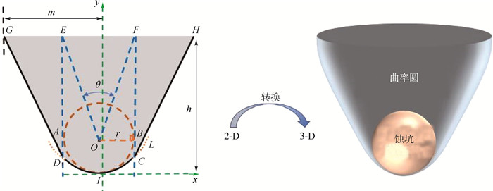
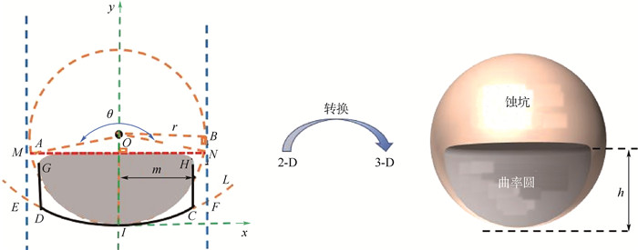
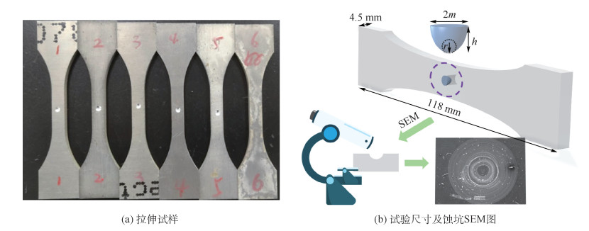
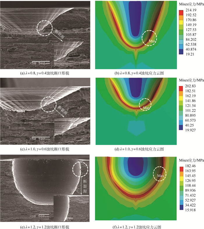
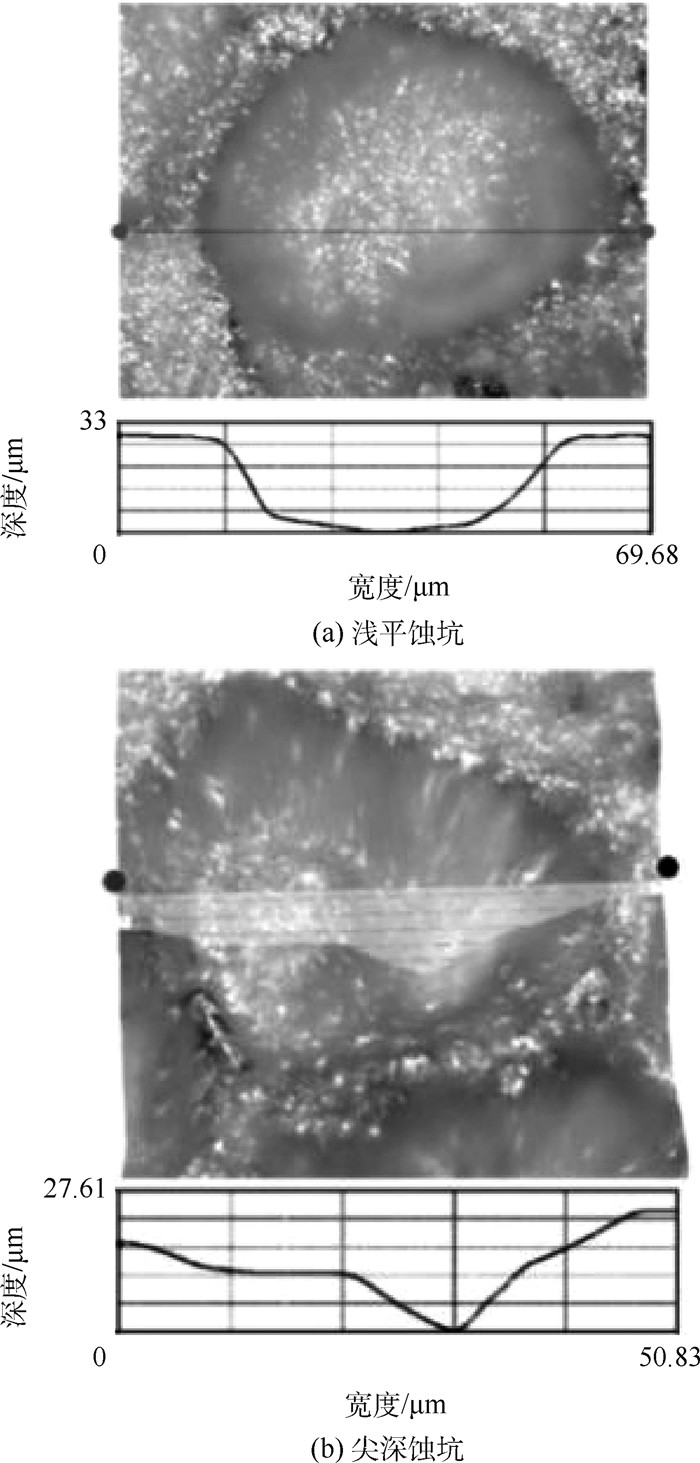
点蚀是腐蚀介质环境中金属性能劣化的主要形式之一。蚀坑导致的应力集中会使结构整体强度退化, 降低结构的安全性和可靠性。因此, 准确的蚀坑模型对结构应力场的分析具有重要影响。为此, 在典型的蚀坑形貌基础上, 结合蚀坑张开角的定义, 提出旋转抛物-锥形蚀坑模型, 并通过有限元仿真与拉伸破坏试验验证了模型的有效性。结果表明:蚀坑导致的应力集中极大值处于接近坑底或坑口区域, 旋转抛物-锥形蚀坑模型在蚀坑坑底、坑肩及坑口处的应力集中分布带比半椭球形蚀坑模型更准确, 应力敏感性更强。
Abstract:As one of the common degradation forms of metal structure exposed to the corrosive medium, pitting may cause the local stress concentration and decrease the strength, reliability and safety of the structure of equipment. Thus, an exact pit model is useful for the stress distribution analysis of the metal structure exposed to the corrosive medium. In this instance, by surveying the pattern of typical corrosive pitting, the concept of pit open angle is redefined, and a novel model called rotating parabolic-conial model is developed. Both FEM simulations and tensile experiments are performed to validate the accuracy and efficiency of the proposed model. It is shown that the maximum of the stress concentration caused by the pitting is generally located around the bottom or mouth area of the pit. Compared with the semi-ellipsoid model, the former is more accurate and sensitive on the description of the stress distribution around the bottom shoulder and mouth of a pit.
-

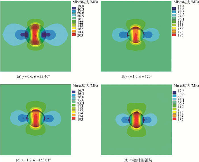
图 10 λ=1.0下的蚀坑局部应力分布
Figure 10. Local stress contribution of corrosion pits under λ=1.0

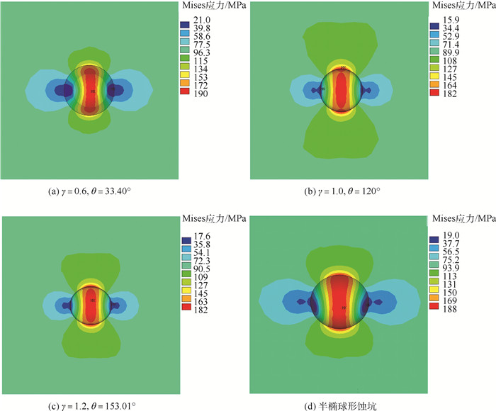
图 11 λ=1.2下的蚀坑局部应力分布
Figure 11. Local stress contribution of corrosion pits under λ=1.2

图 12 应力沿不同λ值的蚀坑截面曲线分布
Figure 12. Stress along corrosion pit sections under various λ value
表 1 理论与数值Mises应力比较
Table 1. Comparison of theoretical and numerical Mises stress
R(垂直拉伸方向上的节点距孔中心距离/mm) 理论Mises应力/MPa 数值Mises应力/MPa 误差/% 0.4 300 301.97 0.66 0.464 220.02 232.21 5.54 0.5 193.44 200.11 3.45  下载: 导出CSV
表 2 旋转抛物-锥形蚀坑与半椭球形蚀坑应力集中系数
Table 2. Stress concentration factors between rotating parabolic-conial corrosion pit and semi-ellipsoid corrosion pits
γ K λ=0.8 λ=1.0 λ=1.2 0.4 2.142 0.6 2.028 0.8 2.128 1.904 1.0 2.152 1.959 1.2 1.934 1.825 1.4 1.818 半椭形蚀坑 2.022 1.866 1.876
下载: 导出CSV
-
[1] 刘治国, 李旭东, 陈川. 单个边缘微观损伤对铝合金材料蚀坑应力集中效应的影响研究[J]. 机械科学与技术, 2021, 40(3): 456-462. doi: 10.13433/j.cnki.1003-8728.20200075LIU Z G, LI X D, CHEN C. Influence of single marginal microcosmic damage on concentration effect of corrosion pit stress for aluminum alloy[J]. Mechanical Science and Technology for Aerospace Engineering, 2021, 40(3): 456-462(in Chinese). doi: 10.13433/j.cnki.1003-8728.20200075 [2] LIU D Z, LI Y, XIE X D, et al. Effect of pre-corrosion pits on residual fatigue life for 42CrMo steel[J]. Materials (Basel, Switzerland), 2019, 12(13): 2130-2137. doi: 10.3390/ma12132130 [3] ISHIHARA S, SAKA S, NAN Z Y, et al. Prediction of corrosion fatigue lives of aluminium alloy on the basis of corrosion pit growth law[J]. Fracture of Engineering Materials and Structures, 2006, 29(6): 472-480. doi: 10.1111/j.1460-2695.2006.01018.x [4] FARHAD F, ZHANG X, SMYTH-BOYLE D. Fatigue behaviour of corrosion pits in X65 steel pipelines[J]. Proceedings of the Institution of Mechanical Engineers, Part C: Journal of Mechanical Engineering Science, 2019, 233(5): 1771-1782. doi: 10.1177/0954406218776338 [5] XIANG L H, PAN J Y, CHEN S Y. Analysis on the stress corrosion crack inception based on pit shape and size of the FV520B tensile specimen[J]. Results in Physics, 2018, 9: 463-470. doi: 10.1016/j.rinp.2018.03.005 [6] HASHIM M, FARHAD F, SMYTH-BOYLE D, et al. Behavior of 316L stainless steel containing corrosion pits under cyclic loading[J]. Materials and Corrosion, 2019, 70(11): 2009-2019. doi: 10.1002/maco.201810744 [7] LI X W, LIANG J S, SHI T, et al. Tribological behaviors of vacuum hot-pressed ceramic composites with enhanced cyclic oxidation and corrosion resistance[J]. Ceramics International, 2020, 46(9): 12911-12920. doi: 10.1016/j.ceramint.2020.02.057 [8] EUBANKS R A. Stress concentration due to a hemispherical pit at a free surface[J]. Journal of Applied Mechanics, 1954, 21(3): 57-62. [9] FUJITA T, SADAVASU T. Stress concentration due to hemispherical pit at a free surface of a thick plate under all around tension[J]. Bulletin of the Japan Society of Mechanical Engineers, 1978, 21(154): 561-565. doi: 10.1299/jsme1958.21.561 [10] CERIT M. Corrosion pit-induced stress concentration in spherical pressure vessel[J]. Thin-Walled Structures, 2019, 136: 106-112. doi: 10.1016/j.tws.2018.12.014 [11] CERIT M. Numerical investigation on torsional stress concentration factor at the semi elliptical corrosion pit[J]. Corrosion Science, 2013, 67: 225-232. doi: 10.1016/j.corsci.2012.10.028 [12] CERIT M, GENEL K, EKSI S. Numerical investigation on stress concentration of corrosion pit[J]. Engineering Failure Analysis, 2009, 16(7): 2467-2472. doi: 10.1016/j.engfailanal.2009.04.004 [13] HOU J, SONG L. Numerical investigation on stress concentration of tension steel bars with one or two corrosion pits[J]. Advances in Materials Science and Engineering, 2015, 2015: 413737. [14] LI J Q. Modelling on the evolution of corrosion pit during stress corrosion[J]. Advances in Petroleum Exploration and Development, 2016, 11(2): 64-69. [15] LIU L, HOU N, DING N, et al. Interacting effects of internal defects and corrosion pits on the stress concentration of hourglass shaped specimens[J]. Journal of Failure Analysis and Prevention, 2019, 19(4): 967-975. doi: 10.1007/s11668-019-00682-2 [16] LI C Q, YANG S T. Stress intensity factors for high aspect ratio semi-elliptical internal surface cracks in pipes[J]. International Journal of Pressure Vessels and Piping, 2012, 96-97(1): 13-23. [17] ATLURI S N, KATHIRESAN K. Influence of flaw shapes on stress intensity factors for pressure vessel surface flaws and nozzle corner cracks[J]. Journal of Pressure Vessel Technology, 1980, 102(3): 278-286. doi: 10.1115/1.3263332 [18] ACUÑA N, GONZÁLEZ-SÁNCHEZ J, KÚ-BASULTO G, et al. Analysis of the stress intensity factor around corrosion pits developed on structures subjected to mixed loading[J]. Scripta Materialia, 2006, 55(4): 363-366. doi: 10.1016/j.scriptamat.2006.04.024 [19] TURNBULL A, WRIGHT L, CROCKER L. New insight into the pit-to-crack transition from finite element analysis of the stress and strain distribution around a corrosion pit[J]. Corrosion Science, 2010, 52(4): 1492-1498. doi: 10.1016/j.corsci.2009.12.004 [20] 张川, 姚卫星. 危险蚀坑评判及疲劳寿命计算[J]. 机械强度, 2013, 35(2): 207-213. https://www.cnki.com.cn/Article/CJFDTOTAL-JXQD201302019.htmZHANG C, YAO W X. Judgment of critical pits and calculation of fatigue life[J]. Journal of Mechanical Strength, 2013, 35(2): 207-213(in Chinese). https://www.cnki.com.cn/Article/CJFDTOTAL-JXQD201302019.htm [21] WANG W G, ZHOU A N, FU G Y, et al. Evaluation of stress intensity factor for cast iron pipes with sharp corrosion pits[J]. Engineering Failure Analysis, 2017, 81: 254-269. doi: 10.1016/j.engfailanal.2017.06.026 [22] 国家市场监督管理总局, 国家标准化管理委员会. 金属材料拉伸试验第1部分: 室温试验方法: GB/T228.1—2021[S]. 北京: 中国标准出版社, 2011: 11-14.State Administration for Market Regulation, Standardization Administtration of the People's Republi of China. Metallic materials-Tensile testing-Part 1: Method of test at room temperature: GB/T 228.1—2021[S]. Beijing: Standards Press of China, 2011: 11-14(in Chinese). -

 下载:
下载:


 点击查看大图
计量
- 文章访问数: 247
- HTML全文浏览量: 73
- PDF下载量: 22
- 被引次数: 0
