


Conducted electromagnetic interference of wireless charging system with bilateral LCC of electric vehicle
-
摘要:
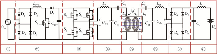
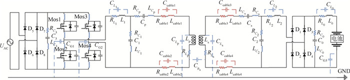
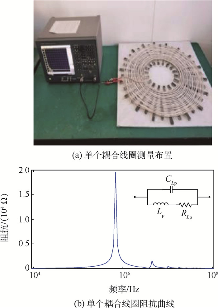
对电动汽车双边LCC拓扑结构无线充电系统传导电磁干扰进行研究,依据标准SAE J2954构建了3.7 kW的无线充电系统传导电磁干扰高频电路模型,采用测量和理论计算结合的方法,提取耦合线圈、线缆和补偿电路元件的高频寄生参数。利用软件ANSYS Maxwell和Simplorer进行系统传导干扰建模仿真分析,通过仿真结果可以看出,在150 kHz~30 MHz频段共模干扰比差模干扰显著。通过系统传导发射试验验证了仿真模型的准确性。
Abstract:The conducted electromagnetic interference of the wireless charging system with the bilateral LCC structure of electric vehicles is studied. According to the standard SAE J2954, a high-frequency circuit model of the conducted electromagnetic interference of the wireless charging system with a power of 3.7 kW is constructed. A method combining measurement and theoretical calculation is used to extract the high-frequency parasitic parameters of the coupling coil, cable and compensation circuit components. The modeling and simulation analysis of the conducted interference of the system are carried out by using the software ANSYS Maxwell and Simplorer. Simulation results show that the common mode interference is more significant than the differential mode interference in the frequency band of 150 kHz-30 MHz. The accuracy of the simulation model is verified by the conducted emission experiment of the wireless charging system.
-

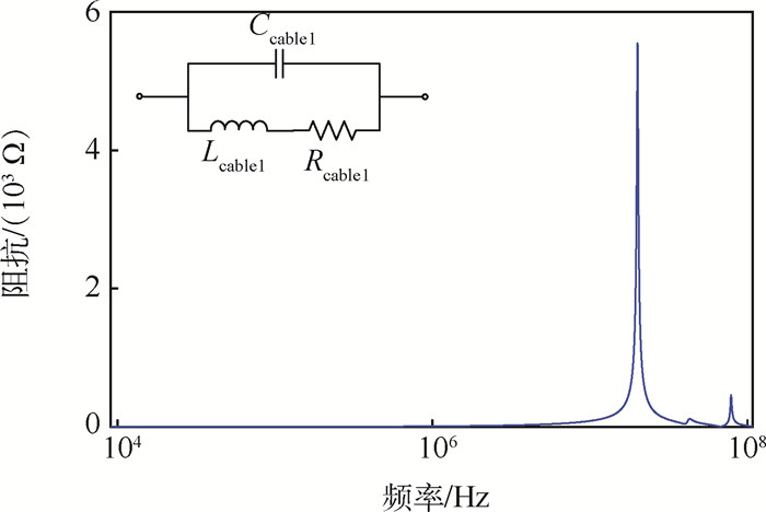
图 9 正极线缆的等效电路及阻抗测量结果
Figure 9. Equivalent circuit and impedance measurement of positive cable

图 10 LCC拓扑的电容和电感的阻抗
Figure 10. Impedances of capacitance and inductance of LCC topology

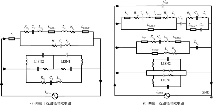
图 12 差模干扰和共模干扰路径等效电路
Figure 12. Equivalent circuits of different mode interference and common mode interference

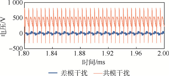
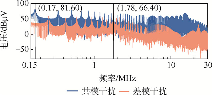
图 14 共模干扰电压和差模干扰电压
Figure 14. Voltage of common mode interference and different mode interference

图 16 无线充电系统传导发射试验布置
Figure 16. Experimental setup of conducted emission of wireless charging system
表 1 无线充电系统的设计指标
Table 1. Design specifications of wireless charger
指标 数值 输入电网电压Uac/V 220 输入电网电压频率f1/Hz 50 PFC输出直流电压Uin/V 260~425 输出充电电压Ub/V 300~400 工作频率f/kHz 81.38~90 最大功率P/kW 3.7  下载: 导出CSV
表 2 电路元件参数
Table 2. Circuit element parameters
元件名称 元件参数或选型 整流二极管 VS-80APS12-M3 PFC升压电感LPFC 500 μH PFC电容CPFC 1 500 μF/600 V PFC二极管 IDW40G65C5SKSA1 逆变功率开关MOSFET IPW65R048CFDA 逆变续流二极管 IDW10G120C5BFKSA7 次级侧滤波电容Co 66 μF/650 V 次级侧滤波电感Lo 158 μH
下载: 导出CSV
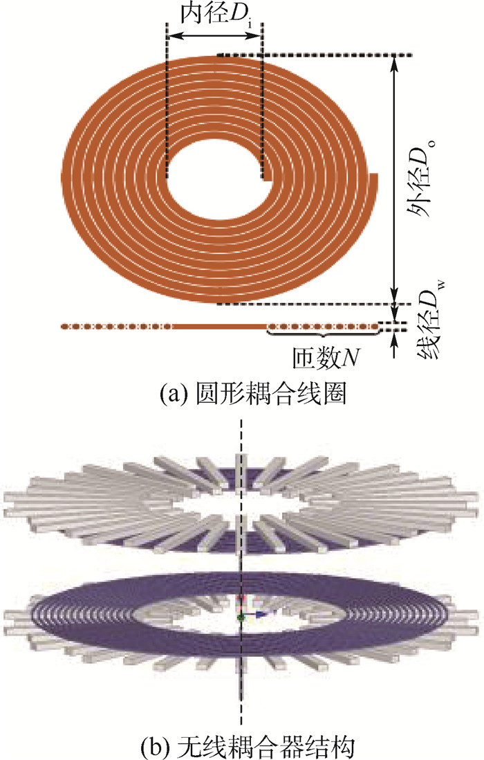
表 3 耦合线圈参数
Table 3. Coupling coil parameters
参数 选型式数值 绕线选型 800股利兹线 绕线材料 II(16AWG4*5X24/36) 绕线直径/mm 3.9 线圈外半径/mm 300 线圈内半径/mm 150 匝数 16 线圈耦合系数 0.352 5
下载: 导出CSV
表 4 铁氧体设计参数
Table 4. Design parameters of ferrite
参数 数值 单位铁氧体尺寸/(mm×mm×mm) 60×15×9 长条铁氧体尺寸/(mm×mm×mm) 240×15×9 短条铁氧体尺寸/(mm×mm×mm) 180×15×9 长条铁氧体数量 18 短条铁氧体数量 18 铁氧体排列夹角/(°) 10
下载: 导出CSV
表 5 MOSFET基本特性参数
Table 5. Basic characteristic parameters of MOSFET
参数 数值 漏源电压/V 700 漏源导通电阻/Ω 0.099 栅极电荷/nC 127 连续漏极电流/A 115 输出能量/μJ 10 体二极管的电流变化率/(A·μs-1) 300
下载: 导出CSV
表 6 各元件电气参数和寄生参数
Table 6. Electrical parameters and parasitic parameters of each component
参数 数值 补偿电感L1、L2/μH 68.96 补偿电感寄生电容CL1、CL2/pH 61.20 补偿电感寄生电阻RL1、RL2/mΩ 463.11 补偿电容C1、C2/nF 52.28 补偿电容寄生电感LC1、LC2/nH 364.06 补偿电容寄生电阻RC1、RC2/mΩ 647.05 补偿电容Cp、Cs/nF 19.97 补偿电容寄生电感LCp、LCs/nH 378.18 补偿电容寄生电阻RCp、RCs/mΩ 420.61 正极线缆寄生电感Lcable1/3/μH 1.96 正极线缆寄生电阻Rcable1/3/mΩ 45.33 正极线缆寄生电容Ccable1/3/pF 69.44 负极线缆寄生电感Lcable2/4/μH 1.88 负极线缆寄生电阻Rcable2/4/mΩ 31.64 负极线缆寄生电容Ccable2/4/pF 70.46 线圈电感Lp、Ls/μH 218.81 线圈电感寄生电阻RLp、RLs/mΩ 205.72 线圈对地寄生电容CLp、CLs/nF 3.63 线圈间寄生电容Cps/nF 21.42
下载: 导出CSV
-
[1] SUH I S, CHO D H, FRANKE J, et al. Wireless charging technology and the future of electric transportation[M]. Warrendale: SAE Intemational, 2015: 1-13. [2] ZHAI L, CAO Y, LIN L W, et al. Mitigation conducted emission strategy based on transfer function from a DC-fed wireless charging system for electric vehicles[J]. Energies, 2018, 11(3): 477-493. doi: 10.3390/en11030477 [3] LU X, WANG P, NIYATO D, et al. Wireless charging technologies: Fundamentals, standards, and network applications[J]. IEEE Communications Surveys & Tutorials, 2016, 18(2): 1413-1452. https://ieeexplore.ieee.org/document/7327131 [4] SAE International. Wireless power transfer for light-duty plug-in/electric vehicles and alignment methodology: T-pull test: SAE J2954[S]. Warrendale: SAE International, 2017. [5] IEC. Electric vehicle wireless power transfer (WPT) systems-Part 2: Specific requirements for communication between electric road vehicle (EV) and infrastructure: IEC TS 61980-2[S]. Geneva: IEC, 2019. [6] WANG Q D, LI W L, KANG J W, et al. Electromagnetic safety evaluation and protection methods for a wireless charging system in an electric vehicle[J]. IEEE Transactions on Electromagnetic Compatibility, 2019, 61(6): 1913-1925. doi: 10.1109/TEMC.2018.2875903 [7] CHEN W T, LIU C H, LEE C, et al. Cost-effectiveness comparison of coupler designs of wireless power transfer for electric vehicle dynamic charging[J]. Energies, 2016, 9(11): 906-918. doi: 10.3390/en9110906 [8] CHO Y, LEE S, KIM D H, et al. Thin hybrid metamaterial slab with negative and zero permeability for high efficiency and low electromagnetic field in wireless power transfer systems[J]. IEEE Transactions on Electromagnetic Compatibility, 2018, 60(4): 1001-1009. doi: 10.1109/TEMC.2017.2751595 [9] ESTEBAN B, SID-AHMED M, KAR N C. A comparative study of power supply architectures in wireless EV charging systems[J]. IEEE Transactions on Power Electronics, 2015, 30(11): 6408-6422. doi: 10.1109/TPEL.2015.2440256 [10] KIM H, SONG C, KIM D H, et al. Coil design and measurements of automotive magnetic resonant wireless charging system for high-efficiency and low magnetic field leakage[J]. IEEE Transactions on Microwave Theory and Techniques, 2016, 64(2): 383-400. https://ieeexplore.ieee.org/document/7387785 [11] YIM S W. Development and demonstration of kW wireless power transmission method electric vehicle charging system[J]. KEPCO Journal on Electric Power and Energy, 2021, 7(2): 215-220. https://www.researchgate.net/publication/304887313_A_development_of_electrical_vehicle_charging_system_using_wireless_power_transfer [12] 靳志芳. 磁耦合谐振式无线电能传输系统线圈的电磁分析与优化设计[D]. 北京: 北京交通大学, 2017: 9-12.JIN Z F. Electromagnetic analysis and optimum design of coil for magnetic resonance coupling wireless power transmission system[D]. Beijing: Beijing Jiaotong University, 2017: 9-12(in Chinese). [13] MILLER J M, ONAR O C, CHINTHAVALI M. Primary-side power flow control of wireless power transfer for electric vehicle charging[J]. IEEE Journal of Emerging and Selected Topics in Power Electronics, 2015, 3(1): 147-162. doi: 10.1109/JESTPE.2014.2382569 [14] CHOI S Y, HUH J, LEE W Y, et al. Asymmetric coil sets for wireless stationary EV chargers with large lateral tolerance by dominant field analysis[J]. IEEE Transactions on Power Electronics, 2014, 29(12): 6406-6420. doi: 10.1109/TPEL.2014.2305172 [15] QI H Y, CHEN W J, SHA Y L, et al. High frequency conducted EMI modeling of a series-series resonant WPT system[C]//2017 IEEE 3rd International Future Energy Electronics Conference and ECCE Asia. Piscataway: IEEE Press, 2017: 2279-2282. -

 下载:
下载:


 点击查看大图
计量
- 文章访问数: 336
- HTML全文浏览量: 110
- PDF下载量: 31
- 被引次数: 0
