


Dual-input dual-Buck aviation static inverter with four-quadrant operation and circulation-free
-
摘要:
航空静止变流器(ASI)是机载电源系统的关键部分,为进一步提升ASI的工作效率和可靠性,在双输入双Buck逆变技术基础上提出一种高效高可靠性无环流ASI拓扑。该拓扑不仅能够四象限运行和部分功率单级传输,而且实现了所有工作模态下桥臂无环流运行。分析了拓扑的四象限运行工作模态、拓扑的等效数学模型等,研究了基于单极性层叠式双载波调制的无环流ASI主功率管的驱动方式。优化了调节器参数,拓展了变流器闭环控制系统的稳定裕度。开展了该拓扑与全桥逆变等拓扑的开关损耗、工作效率等方面的实验研究。结果表明:该拓扑及其控制方法正确可行,部分功率实现了单级传输,工作效率高,并且具有无桥臂直通风险、无需体二极管续流等优点,为高效高可靠性航空静止变流技术奠定了基础。
Abstract:The aviation static inverter (ASI) is a key part of the airborne power system, and inorder to further improve the efficiency and reliability of the ASI, an efficient and Ihighly reliable circulation-free ASI topology is proposed on the basis of thedual-input dual-Buck inverter technology. The topology not only can operate in four quadrants and transmit part of the power at a single stage, but also achieves circulation-free operation of the bridge arm in all working modes. In this paper, the four quadrant operation mode and the equivalent mathematical model of the topology are analyzed in detail. The driving mode of the main power transistor of the circulation-free ASI based on the mono-polar cascade double carrier modulation is studied. The parameter optimization of the regulator is studied, and the stability margin of the converter closed-loop control system is expanded. Experimental research on the switching loss and efficiency of this topology and full bridge inverter is carried out. The results show that the topology and its control method are correct and feasible, and part of the power can be transmitted in a single stage with high efficiency. And it has the advantages of no bridge arm through risk and no body diode freewheeling. It lays a foundation for high efficiency and high-reliability aviation static converter technology.
-
Key words:
- circulation-free /
- aviation static converter /
- five level /
- four quadrants /
- dual carrier modulation
-

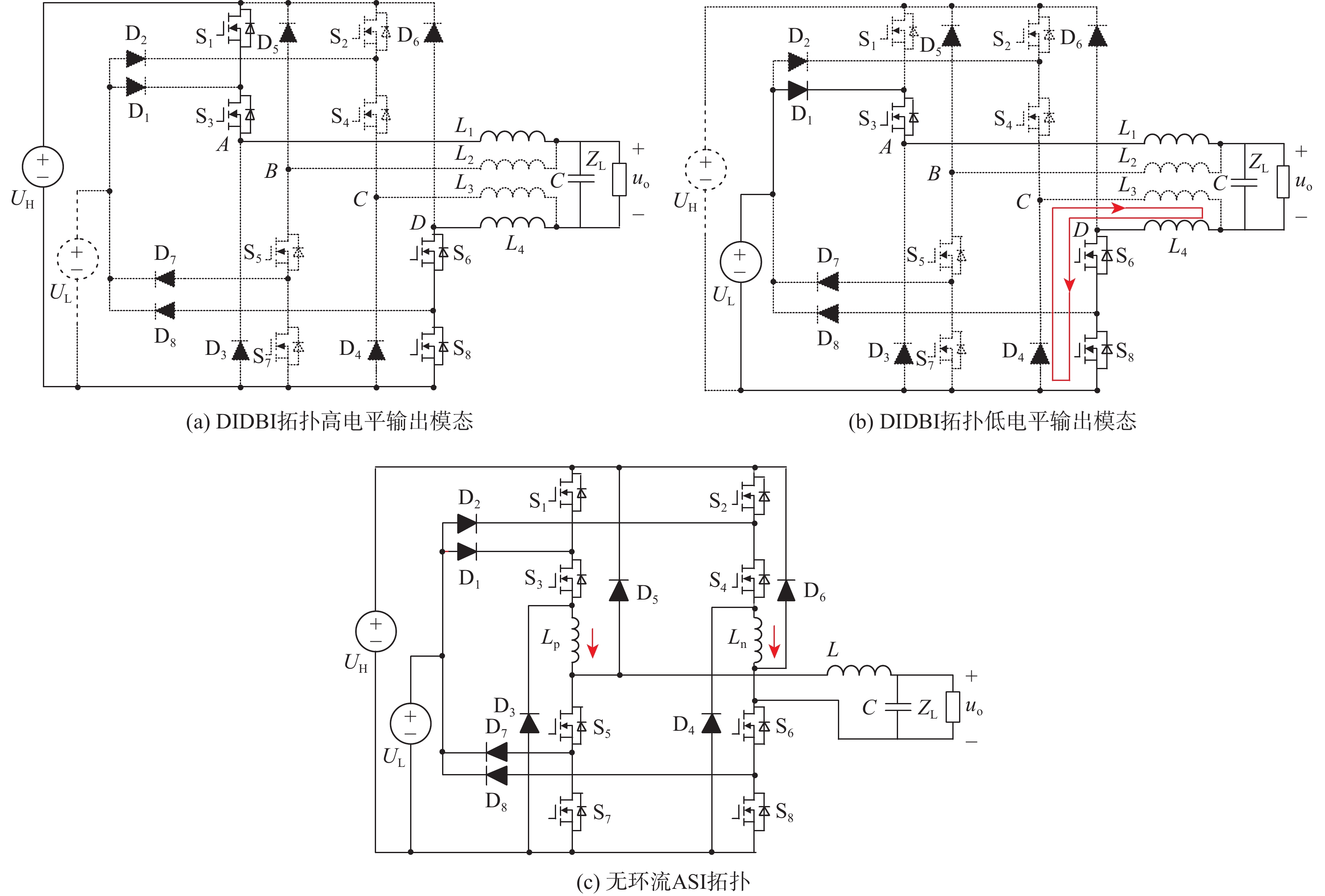
图 1 DIDBI导通模态和无环流ASI拓扑
Figure 1. DIDBI conduction mode and circulation-free ASI topology

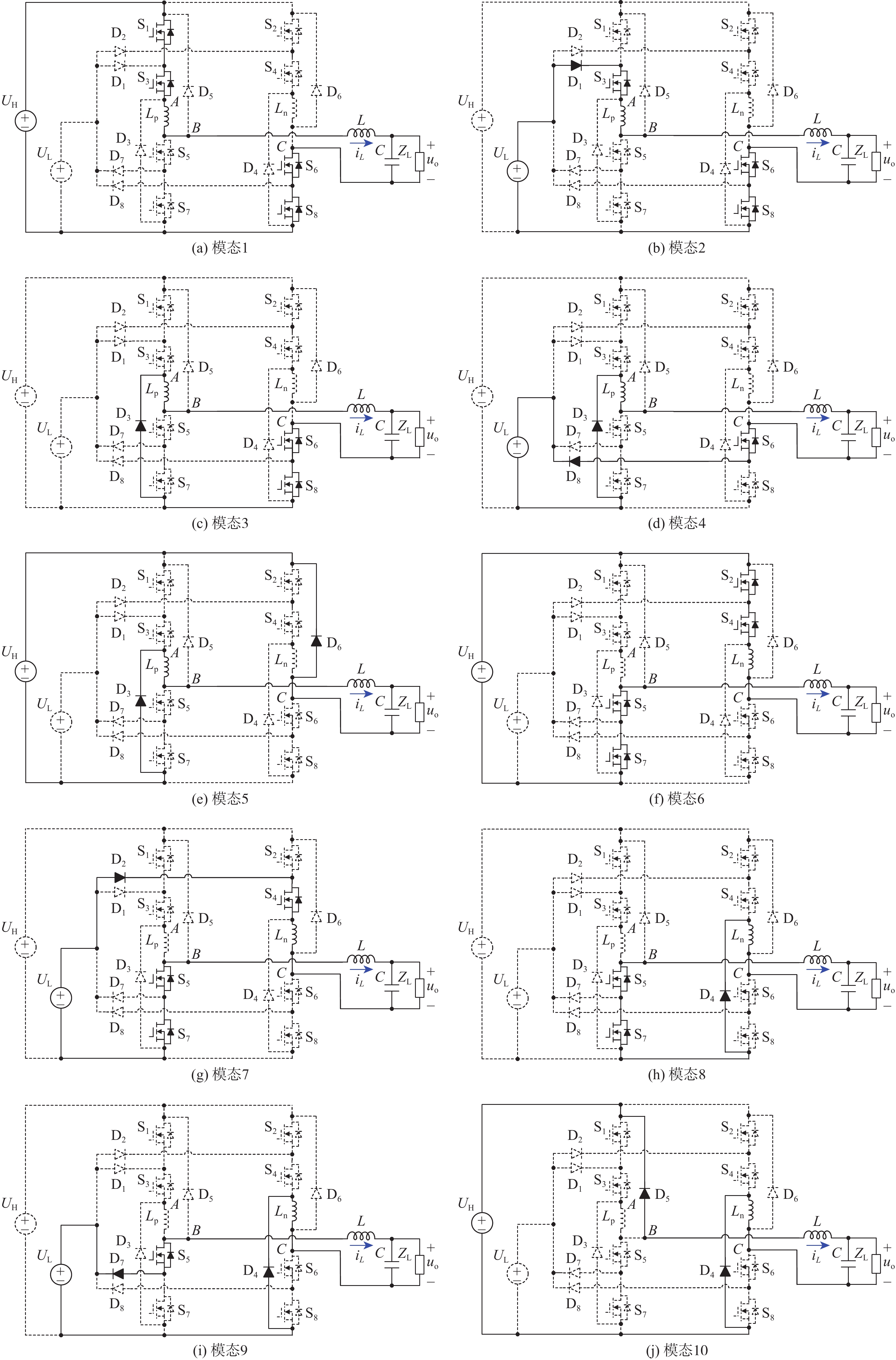
图 2 无环流ASI四象限运行工作模态
Figure 2. Operating modes of circulation-free ASI four-quadrant runtime

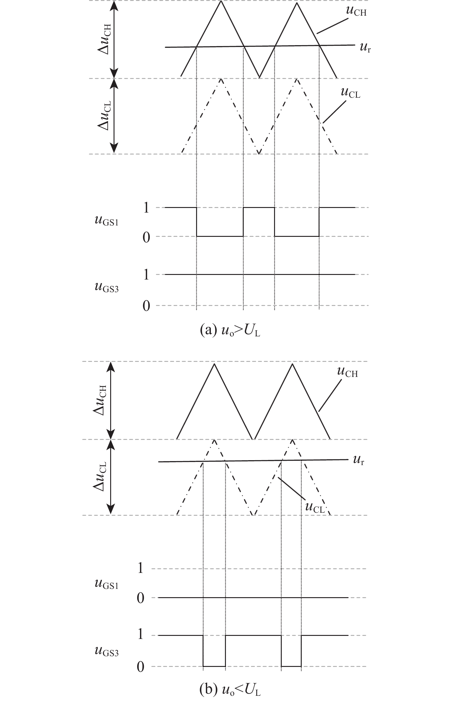
图 5 采用电压前馈的无环流ASI双闭环控制
Figure 5. Circulation-free ASI double closed loop control using voltage feed forward
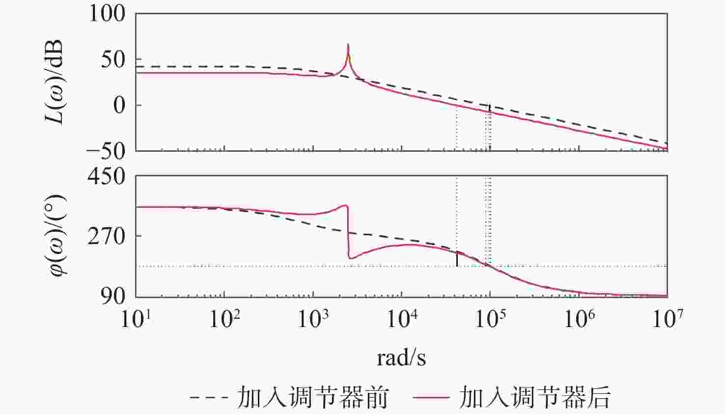
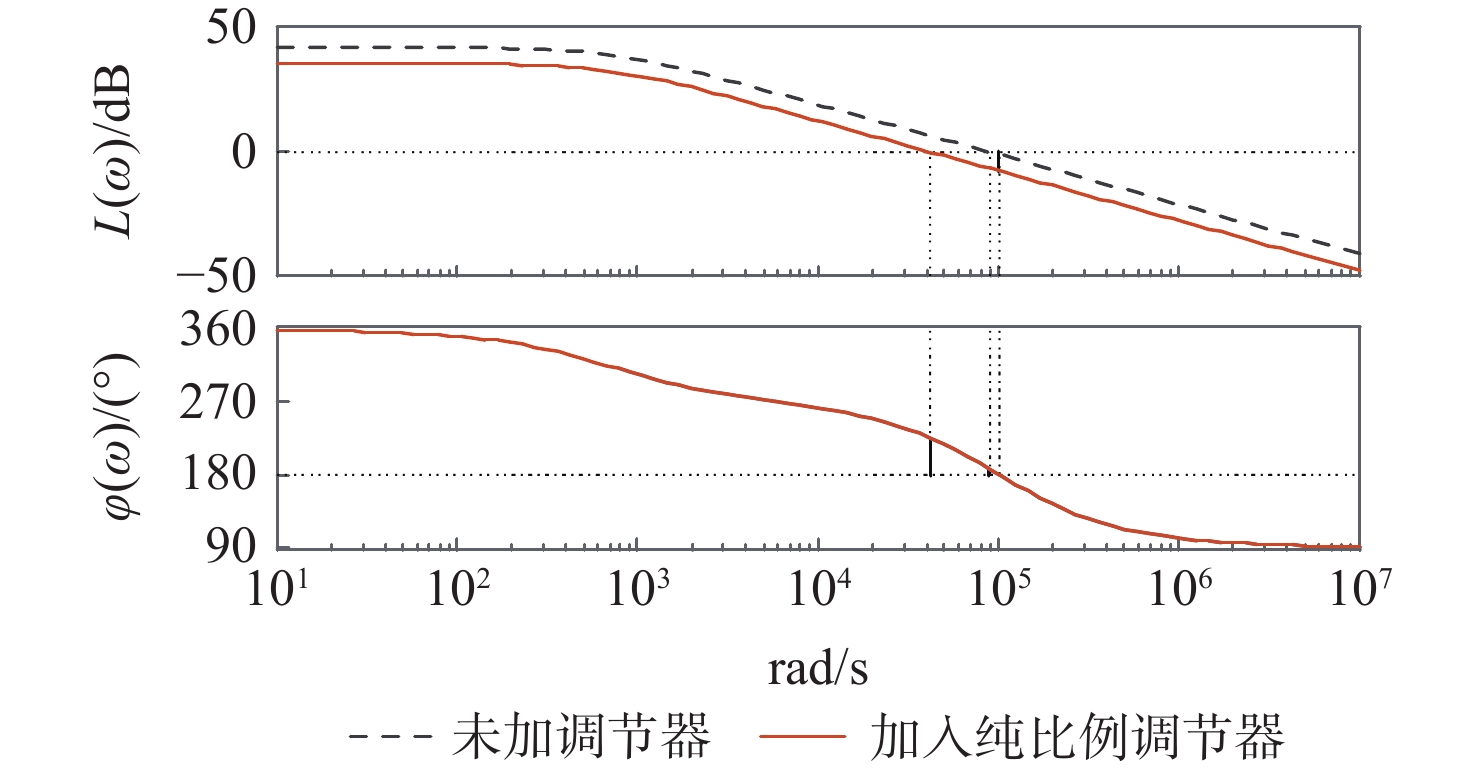
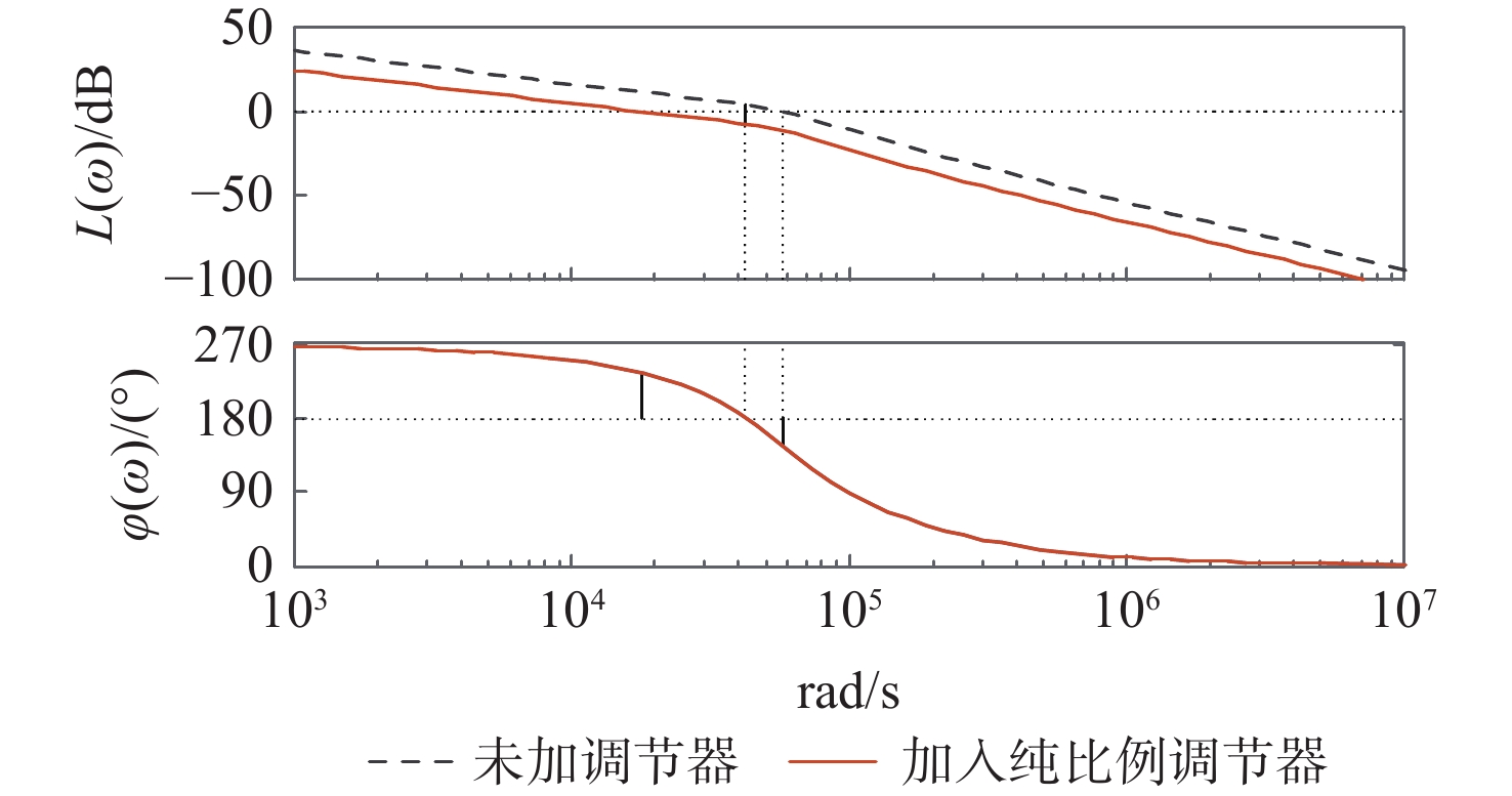
图 8 ASI拓扑的开环电流内环Bode图
Figure 8. Open loop current inner loop Bode diagram of ASI topology
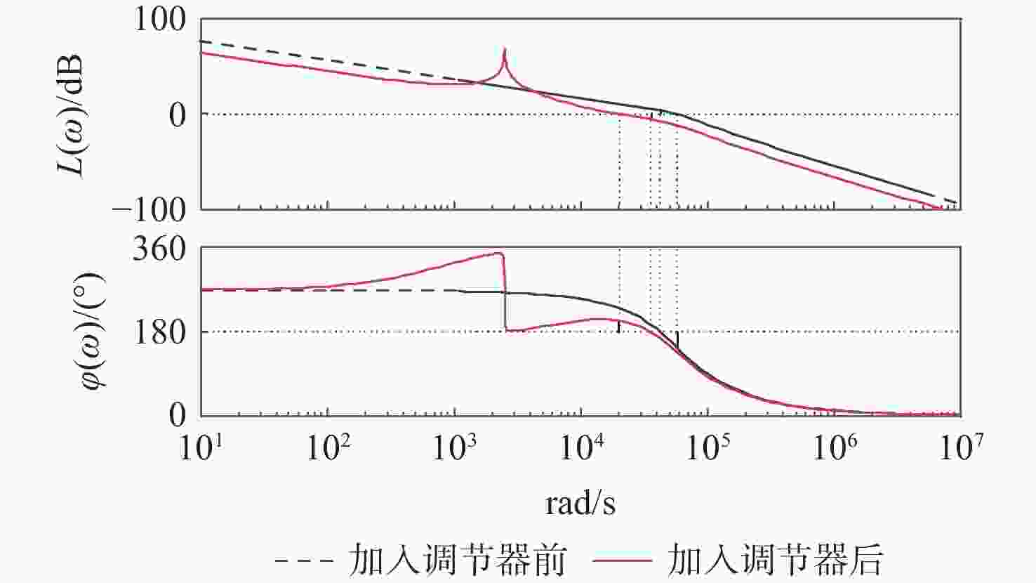
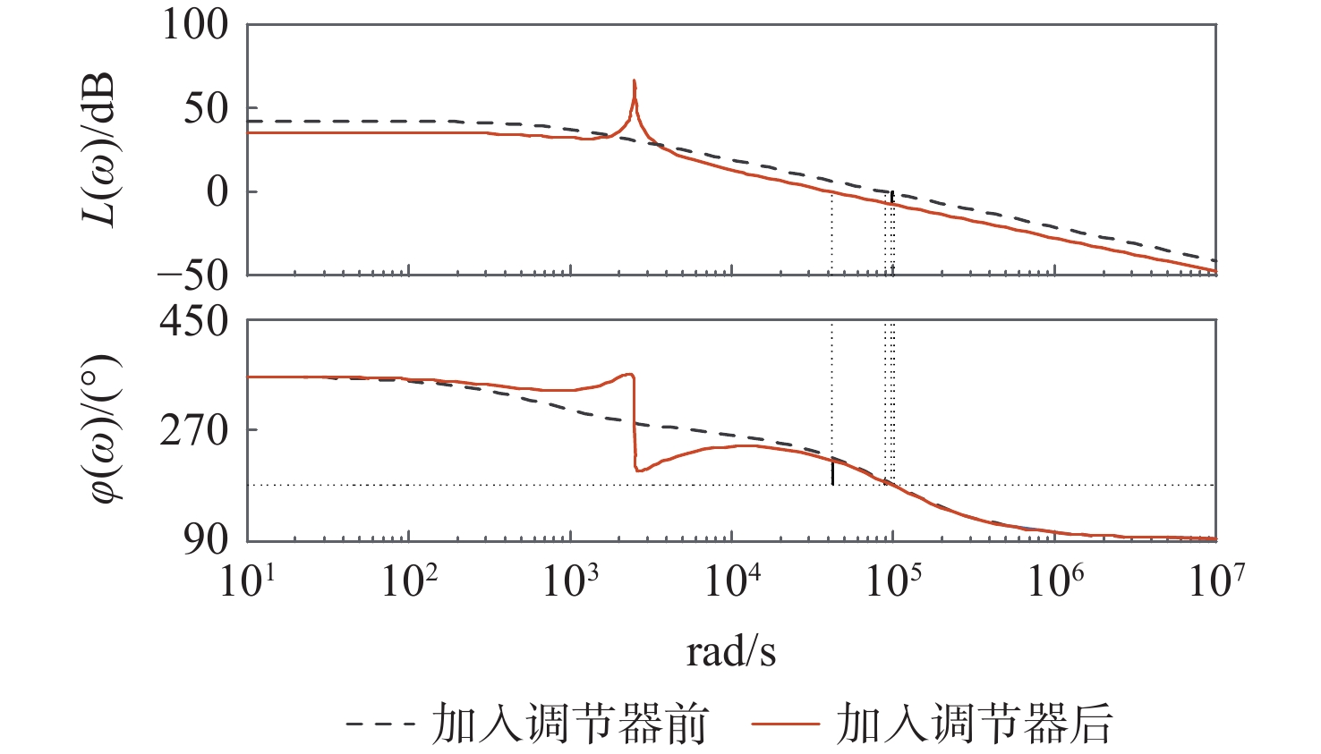
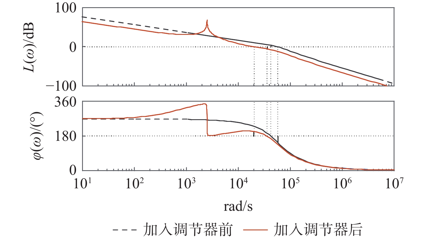
图 11 ASI拓扑的开环电压外环Bode图
Figure 11. Open loop voltage outer loop Bode diagram of ASI topology
表 1 四象限与各模态对应关系
Table 1. Four quadrants corresponding to each mode
象限 模态 象限Ⅰ(iL>0,uo>0)uo>UL 模态1 象限Ⅰ(iL>0,uo>0)uo<UL 模态2 象限Ⅱ(iL>0,uo<0)−uo<UL 模态3 象限Ⅱ(iL>0,uo<0)−uo>UL 模态4 模态5 象限Ⅲ(iL<0,uo<0)−uo>UL 模态6 象限Ⅲ(iL<0,uo<0)−uo<UL 模态7 象限Ⅳ(iL<0,uo>0)uo<UL 模态8 象限Ⅳ(iL<0,uo>0)uo>UL 模态9 模态10  下载: 导出CSV
表 2 控制器参数
Table 2. Controller parameters
控制环 ωo/(rad·s−1) ωc/(rad·s−1) kip kir 相位裕度/(°) 开环截止频率/kHz 基波频率处的增益/dB 电流内环 2512 19 0.417 100 45.3 6.68 66.4 电压外环 2512 19 0.493 150 63 3.38 68.5
下载: 导出CSV
-
[1] NGUYEN B L H, CHA H, KIM H G. Single-phase six-switch dual-output inverter using dual-buck structure[J]. IEEE Transactions on Power Electronics, 2018, 33(9): 7894-7903. doi: 10.1109/TPEL.2017.2774363 [2] ALI KHAN A, CHA H, LAI J S. Cascaded dual-buck inverter with reduced number of inductors[J]. IEEE Transactions on Power Electronics, 2018, 33(4): 2847-2856. doi: 10.1109/TPEL.2017.2701400 [3] AKBAR F, CHA H, AHMED H F, et al. A family of single-stage high-gain dual-buck split-source inverters[J]. IEEE Journal of Emerging and Selected Topics in Power Electronics, 2020, 8(2): 1701-1713. doi: 10.1109/JESTPE.2019.2894384 [4] HONG F, LIU J, JI B J, et al. Single inductor dual buck full-bridge inverter[J]. IEEE Transactions on Industrial Electronics, 2015, 62(2): 4869-4877. [5] YAO Z L, XIAO L. Two-switch dual-buck grid-connected inverter with hysteresis current control[J]. IEEE Transactions on Power Electronics, 2012, 27(7): 3310-3318. doi: 10.1109/TPEL.2011.2179318 [6] ZHANG X G, ZHANG L, ZHANG Y C. Model predictive current control for pmsm drives with parameter robustness improvement[J]. IEEE Transactions on Power Electronics, 2019, 34(2): 1645-1657. doi: 10.1109/TPEL.2018.2835835 [7] HUANG Q Y, HUANG A Q. Variable frequency average current mode control for ZVS symmetrical dual-buck H-bridge all-GaN inverter[J]. IEEE Journal of Emerging and Selected Topics in Power Electronics, 2020, 8(4): 4416-4427. doi: 10.1109/JESTPE.2019.2940270 [8] NGUYEN T T, CHA H, NGUYEN B L H, et al. A novel single-phase three-level dual-buck inverter[J]. IEEE Transactions on Power Electronics, 2020, 35(4): 3365-3376. doi: 10.1109/TPEL.2019.2932890 [9] HONG F, LIU J, JI B J, et al. Interleaved dual buck full-bridge three-level inverter[J]. IEEE Transactions on Power Electronics, 2016, 31(2): 964-974. doi: 10.1109/TPEL.2015.2421295 [10] ZHANG L, SUN K, XING Y, et al. A family of five-level dual buck full bridge inverters for grid-tied applications[J]. IEEE Transactions on Power Electronics, 2016, 31(10): 7029-7042. [11] YANG F, GE H J, YANG J F, et al. A family of dual-buck inverters with an extended low-voltage DC-input port for efficiency improvement based on dual-input pulsating voltage-source cells[J]. IEEE Transactions on Power Electronics, 2018, 33(4): 3115-3128. doi: 10.1109/TPEL.2017.2706762 [12] YANG F, GE H J, YANG J F, et al. Dual-input grid-connected photovoltaic inverter with two integrated DC-DC converters and reduced conversion stages[J]. IEEE Transactions on Energy Conversion, 2019, 34(1): 292-301. doi: 10.1109/TEC.2018.2878893 [13] 杨帆, 葛红娟, 党润芸, 等. 一种双直流输入多电平双Buck逆变器[J]. 电工技术学报, 2018, 33(6): 1320-1327. doi: 10.19595/j.cnki.1000-6753.tces.161331YANG F, GE H J, DANG R Y, et al. A dual-DC-input multi-level dual-Buck inverter[J]. Transactions of China Electrotechnical Society, 2018, 33(6): 1320-1327(in Chinese). doi: 10.19595/j.cnki.1000-6753.tces.161331 [14] 于兆龙, 葛红娟, 李尚, 等. Boost电路开关瞬间电压尖峰产生机理及抑制方法[J]. 北京航空航天大学学报, 2020, 46(1): 198-209. doi: 10.13700/j.bh.1001-5965.2019.0154YU Z L, GE H J, LI S, et al. Mechanism of voltage spike production during switching transients and its suppression methods in Boost converter[J]. Journal of Beijing University of Aeronautics and Astronautics, 2020, 46(1): 198-209(in Chinese). doi: 10.13700/j.bh.1001-5965.2019.0154 [15] AZER P, EMADI A. Generalized state space average model for multi-phase interleaved buck, boost and buck-boost DC-DC converters: Transient, steady-state and switching dynamics[J]. IEEE Access, 2020, 8: 77735-77745. doi: 10.1109/ACCESS.2020.2987277 [16] JIANG T Y, JU P, WANG C, et al. Coordinated control of air conditioning loads for system frequency regulation[J]. IEEE Transactions on Smart Grid, 2021, 12(1): 548-560. doi: 10.1109/TSG.2020.3022010 [17] 张瑾, 齐铂金, 张少如. 单相Z源逆变器控制策略[J]. 北京航空航天大学学报, 2010, 36(3): 357-362. doi: 10.13700/j.bh.1001-5965.2010.03.017ZHANG J, QI B J, ZHANG S R. Control strategy for single-phase Z-source inverter[J]. Journal of Beijing University of Aeronautics and Astronautics, 2010, 36(3): 357-362(in Chinese). doi: 10.13700/j.bh.1001-5965.2010.03.017 [18] MIRSAEIDI S, TZELEPIS D, HE J, et al. A controllable thyristor based commutation failure inhibitor for LCC-HVDC transmission systems[J]. IEEE Transactions on Power Electronics, 2021, 36(4): 3781-3792. doi: 10.1109/TPEL.2020.3021284 [19] 李正明, 张国松, 方聪聪. 增强型开关电感准Z源逆变器[J]. 北京航空航天大学学报, 2016, 42(9): 1803-1811. doi: 10.13700/j.bh.1001-5965.2015.0579LI Z M, ZHANG G S, FANG C C. Enhanced switched-inductor quasi-Z-source inverter[J]. Journal of Beijing University of Aeronautics and Astronautics, 2016, 42(9): 1803-1811(in Chinese). doi: 10.13700/j.bh.1001-5965.2015.0579 [20] 王亭岭, 熊军华, 张瑾. 基于预设载波的随机开关频率调制方法[J]. 北京航空航天大学学报, 2013, 39(3): 355-360. doi: 10.13700/j.bh.1001-5965.2013.03.028WANG T L, XIONG J H, ZHANG J. Random PWM method based on pre-determined carrier frequencies[J]. Journal of Beijing University of Aeronautics and Astronautics, 2013, 39(3): 355-360(in Chinese). doi: 10.13700/j.bh.1001-5965.2013.03.028 -

 下载:
下载:


 点击查看大图
计量
- 文章访问数: 240
- HTML全文浏览量: 46
- PDF下载量: 17
- 被引次数: 0
