


Design and aerodynamic analysis of blended wing body with variable camber technology
-
摘要:
变弯度机翼在提高常规布局客机气动特性方面有较大的潜力,但也会引起全机俯仰力矩变化,考虑翼身融合布局飞行器力臂短、配平阻力较大的特点,研究变弯度技术在翼身融合布局飞行器上的减阻收益与配平惩罚。从工程实际出发,采用基于舵面偏转的方式实现后缘变弯度并对比分析不同展向位置处舵面的配平能力;然后利用全局优化方法开展变弯度气动减阻优化设计;最后对变弯度设计空间进行探索。结果表明:随着升力系数的改变,产生配平阻力最小的舵面位置也会发生变化。当不考虑俯仰力矩配平约束时,采用变弯度技术至多可以获得4.62%的减阻收益;在考虑俯仰力矩配平约束后,相比于采用中央体后缘舵面配平,采用变弯度技术至少能够减小2.4×10⁻⁴的配平损失。不同升力系数下,变弯度的舵面偏转组合方式存在明显差异,小升力系数下,多个舵面负偏的变弯度组合有利于减阻并增加抬头力矩;而大升力系数下则是通过多个舵面正偏的组合实现减阻,但会导致低头力矩增加。基于多舵面组合偏转的变弯度减阻收益与力矩惩罚评估,能为工程上设计可变弯度翼身融合布局飞行器提供参考。
Abstract:The variable camber wing has great potential to improve the aerodynamic characteristics of conventional tube and wing design, but it can change the pitching moment of the whole aircraft. The drag reduction advantage and trim penalty of variable camber technology on a blended wing-body aircraft are explored, taking into account the features of short moment arm and substantial trim loss in the blended wing body. Considering the engineering practice, the variable camber of the trailing edge is realized based on flap deflection, and the trimming ability of the flap at different spanwise positions is compared and analyzed. Then, the global optimization method is used to carry out the optimization design of variable camber aerodynamic drag reduction; finally, the variable camber design space is explored. The results show that as the lift coefficient changes, the position of the flap that produces the least trim resistance also changes. Without the pitching moment trim constraint, at most 4.62% of the drag reduction benefit can be obtained by using the variable camber technology. When compared to trimming with the center body's trailing edge, variable camber technology can result in a trim loss of 2.4×10⁻⁴ when it comes to the pitching moment trim constraint.Under different lift coefficients, there are obvious differences in the deflection combination of flaps with variable camber. When the lift coefficient is small, the variable camber can decrease drag by combining the deflection of multiple flap negative deflections, which will increase the head-up moment. When the lift coefficient is large, however, the variable camber can decrease drag by combining the deflection of multiple flap positive deflections. The evaluation of variable camber drag reduction benefit and moment penalty based on the combined deflection of flaps can provide a reference for the engineering design of variable camber blended wing body aircraft.
-
Key words:
- blended wing body /
- variable camber wing /
- aerodynamic performance /
- optimal design /
- surrogate model
-
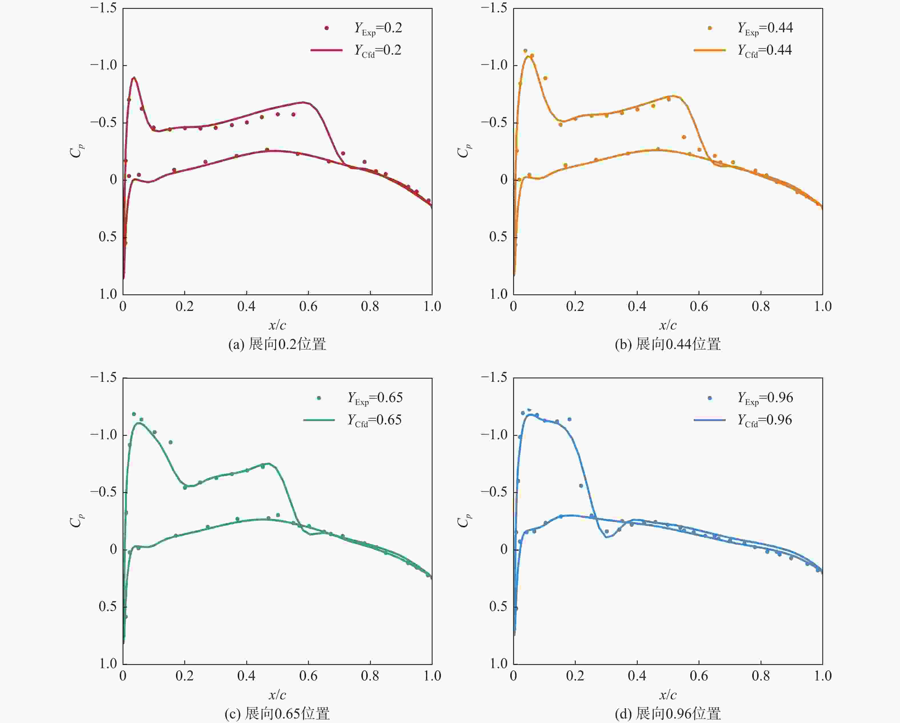
图 2 M6 机翼计算结果与实验数据对比
Figure 2. Comparison of M6 wing calculation results with experimental data
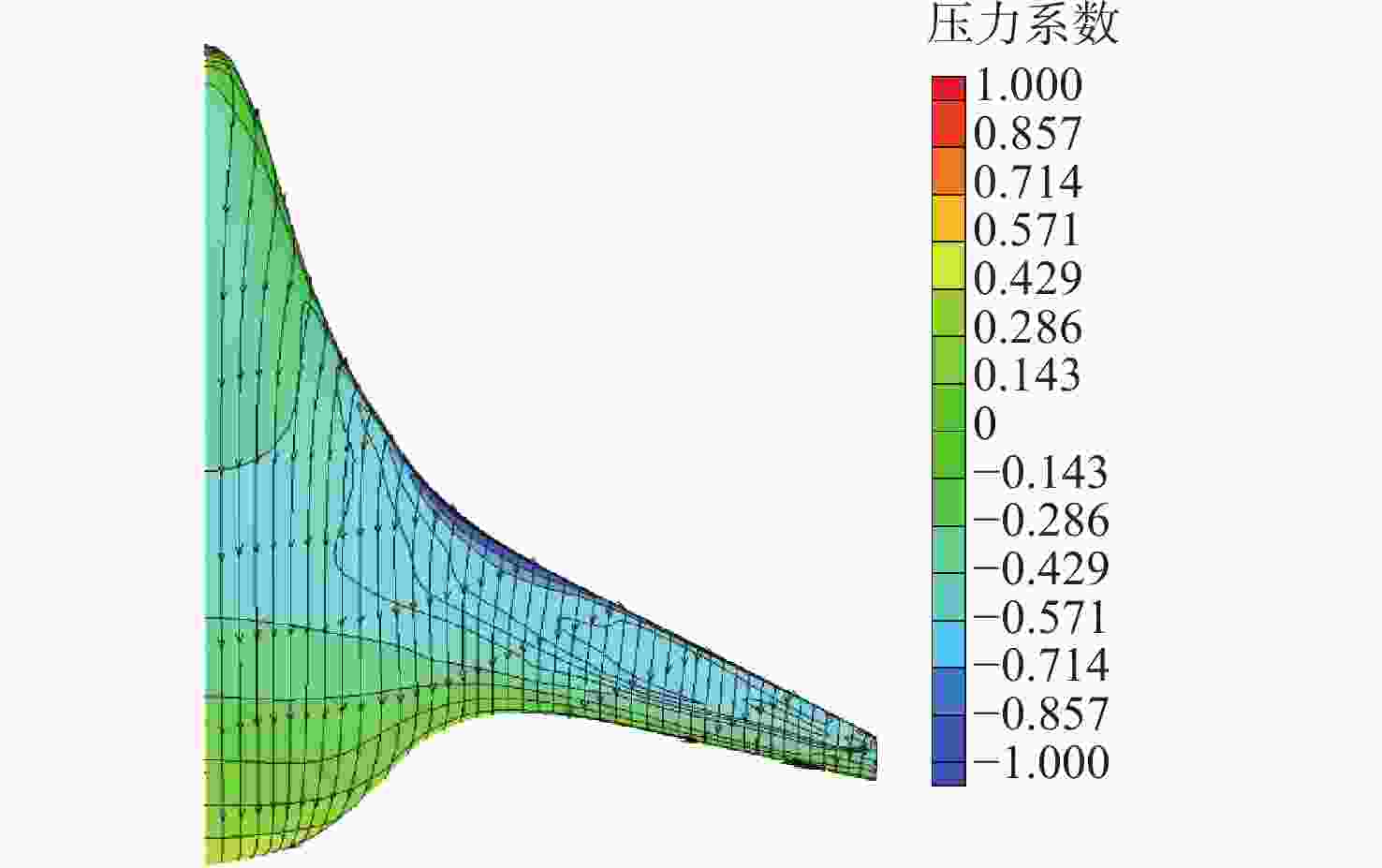
图 8 $Ma = 0.84,\;{C_L} = 0.19$基准构型表面压力及流线图
Figure 8. Surface pressure and streamline diagram of baseline configuration ($Ma = 0.84,\;{C_L} = 0.19$)
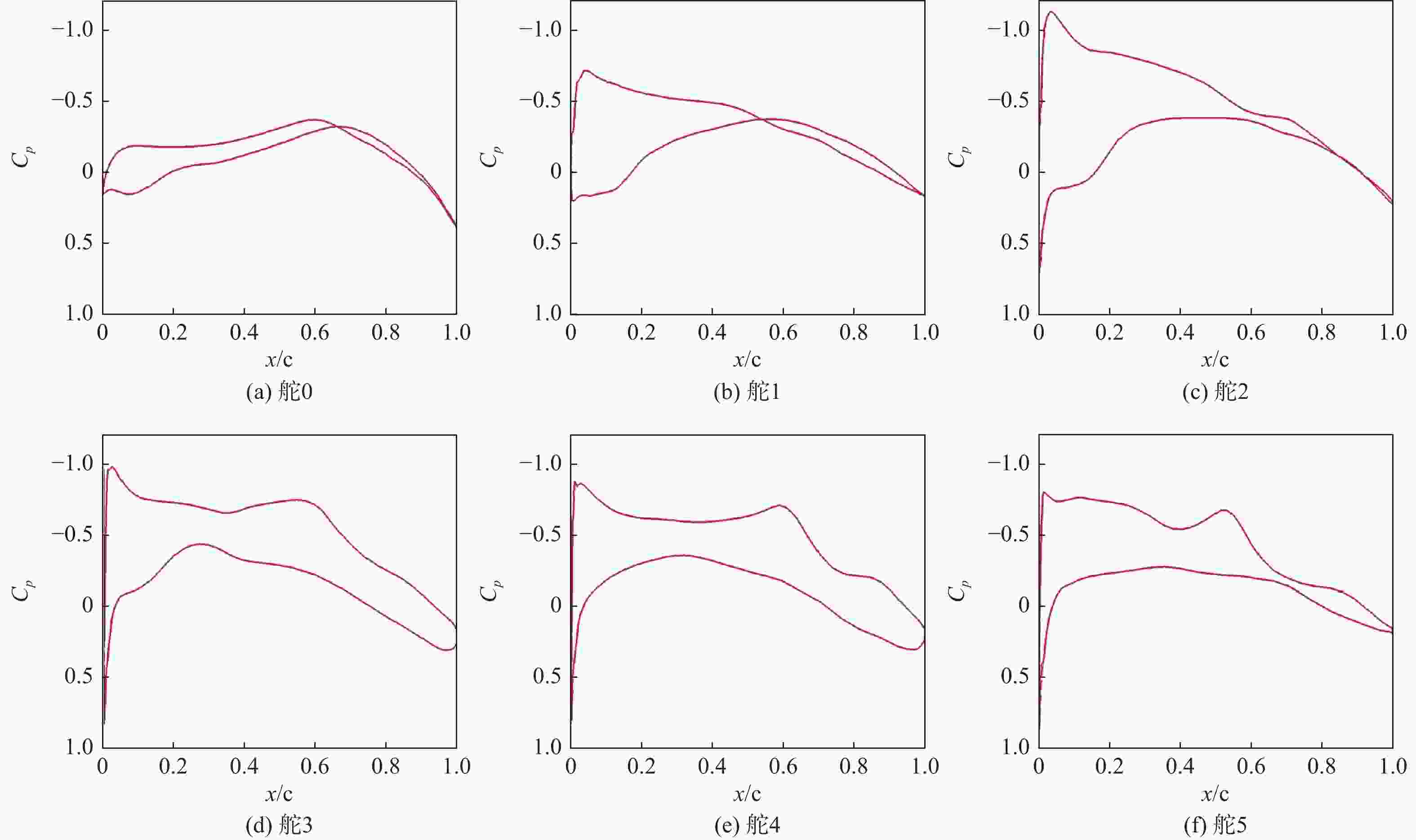
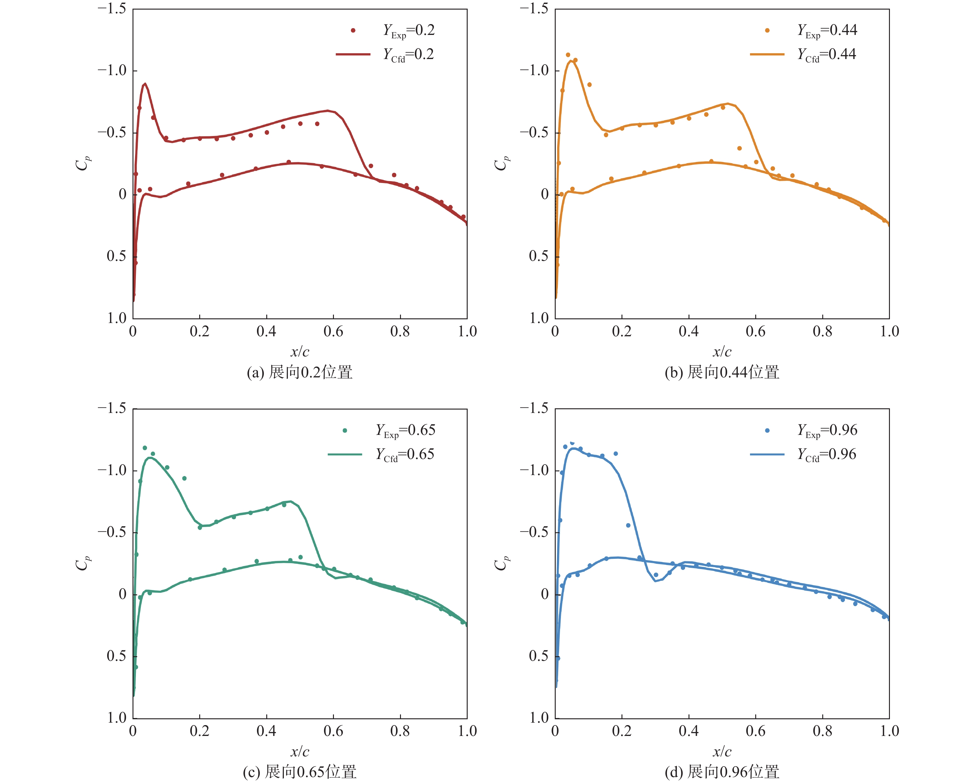
图 9 $Ma = 0.84,\;{C_L} = 0.19$基准构型剖面压力系数
Figure 9. Pressure coefficient of baseline configuration ($Ma = 0.84,\;{C_L} = 0.19$)
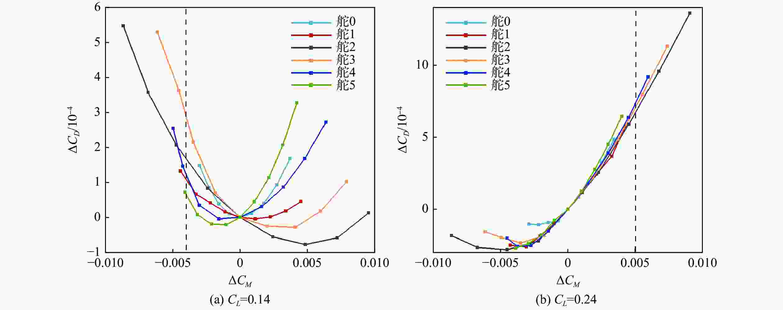
图 10 各舵单偏时阻力与俯仰力矩变化曲线
Figure 10. Curves of drag and pitching moment variation when each flap deflects independently

图 11 ${C_L} = 0.14$时基准构型与单舵面配平构型对比
Figure 11. Comparison of baseline configuration and single flap trim configuration (${C_L} = 0.14$)

图 12 ${C_L} = 0.24$时基准构型与单舵面配平构型对比
Figure 12. Comparison of the baseline configuration and single flap trim configuration(${C_L} = 0.24$)
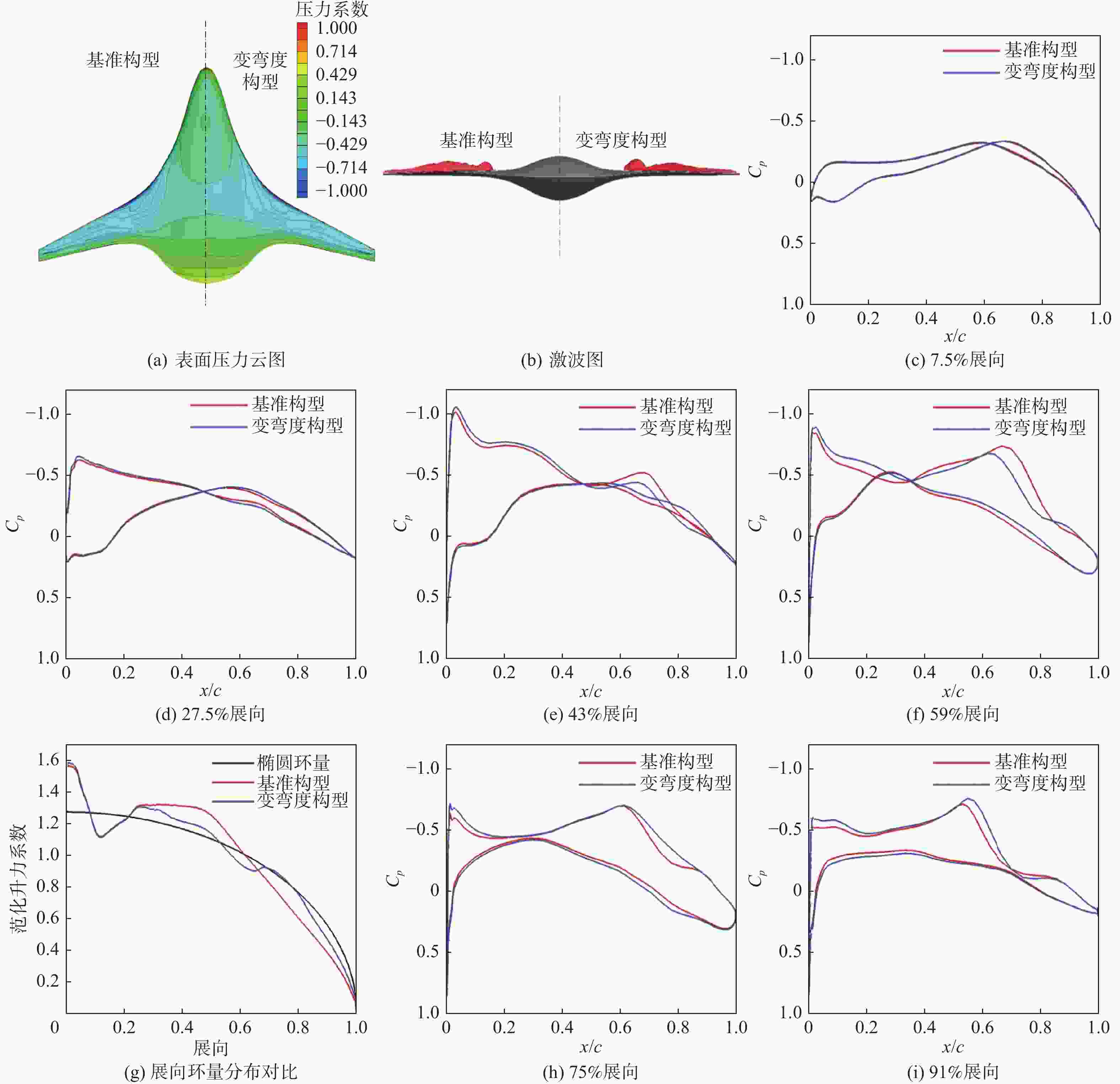
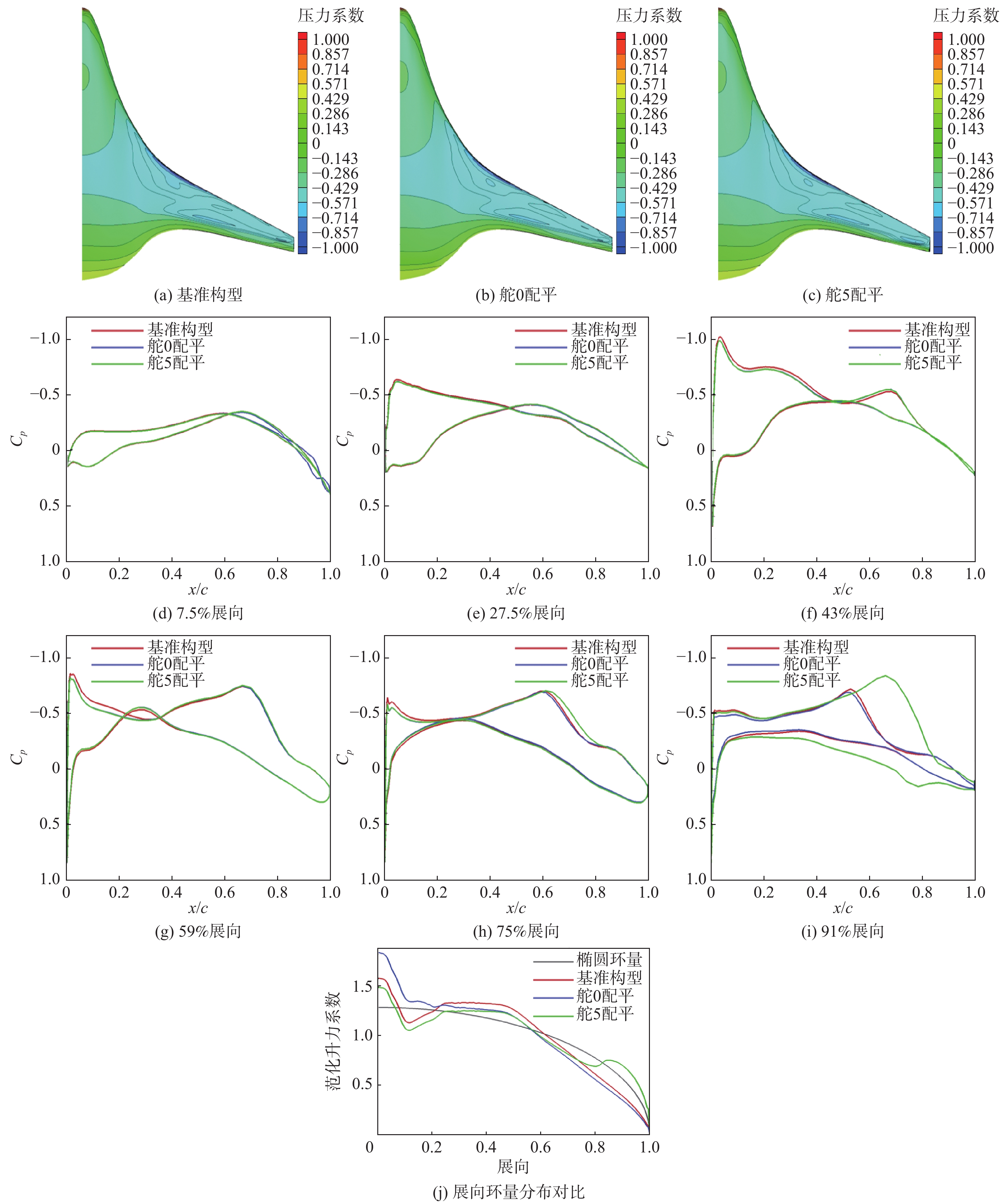
图 13 ${C_L} = 0.14$时不考虑俯仰配平时变弯度前后对比
Figure 13. Comparison of the baseline configuration and variable camber configuration without considering pitch trim (${C_L} = 0.14$)
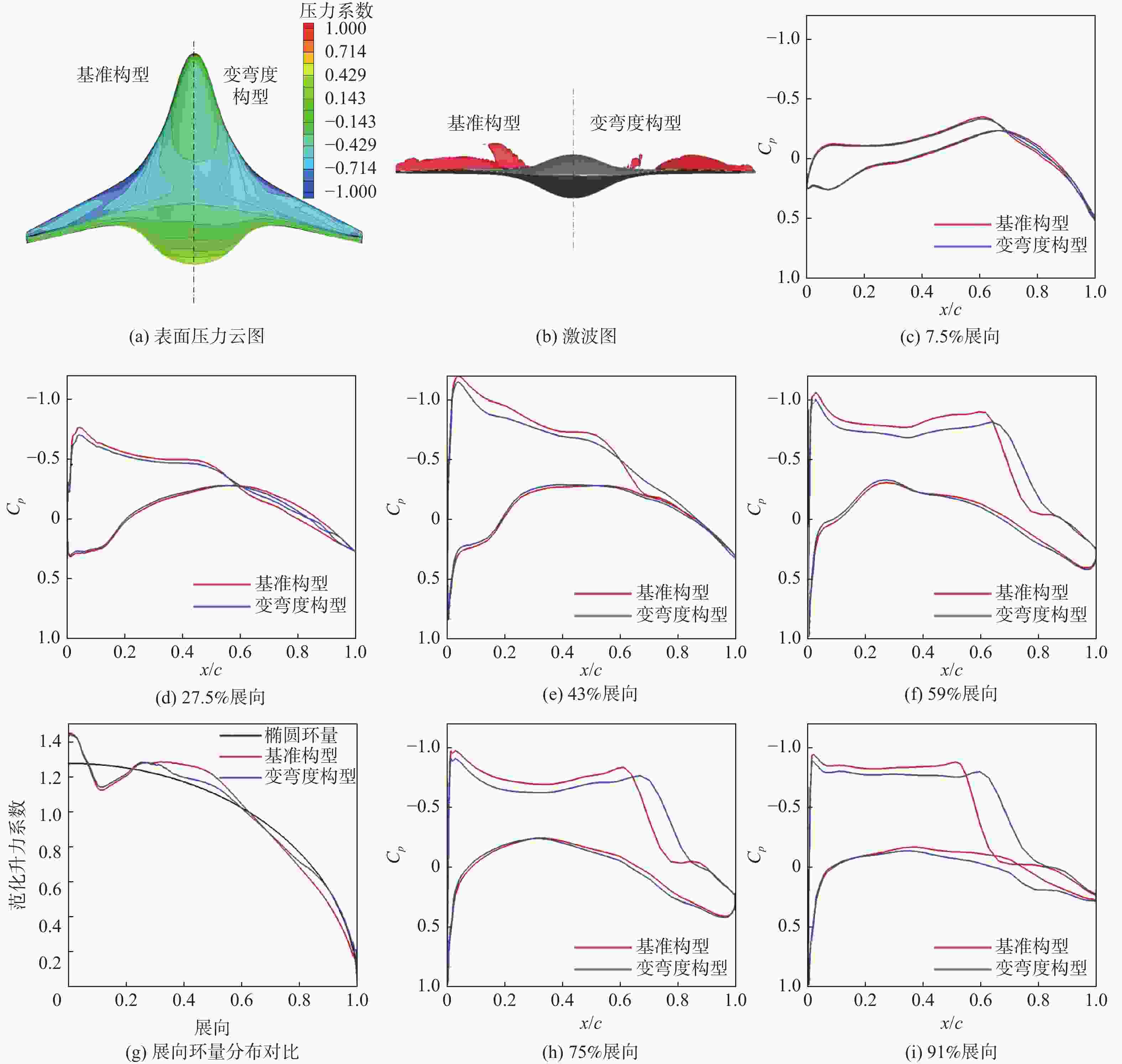
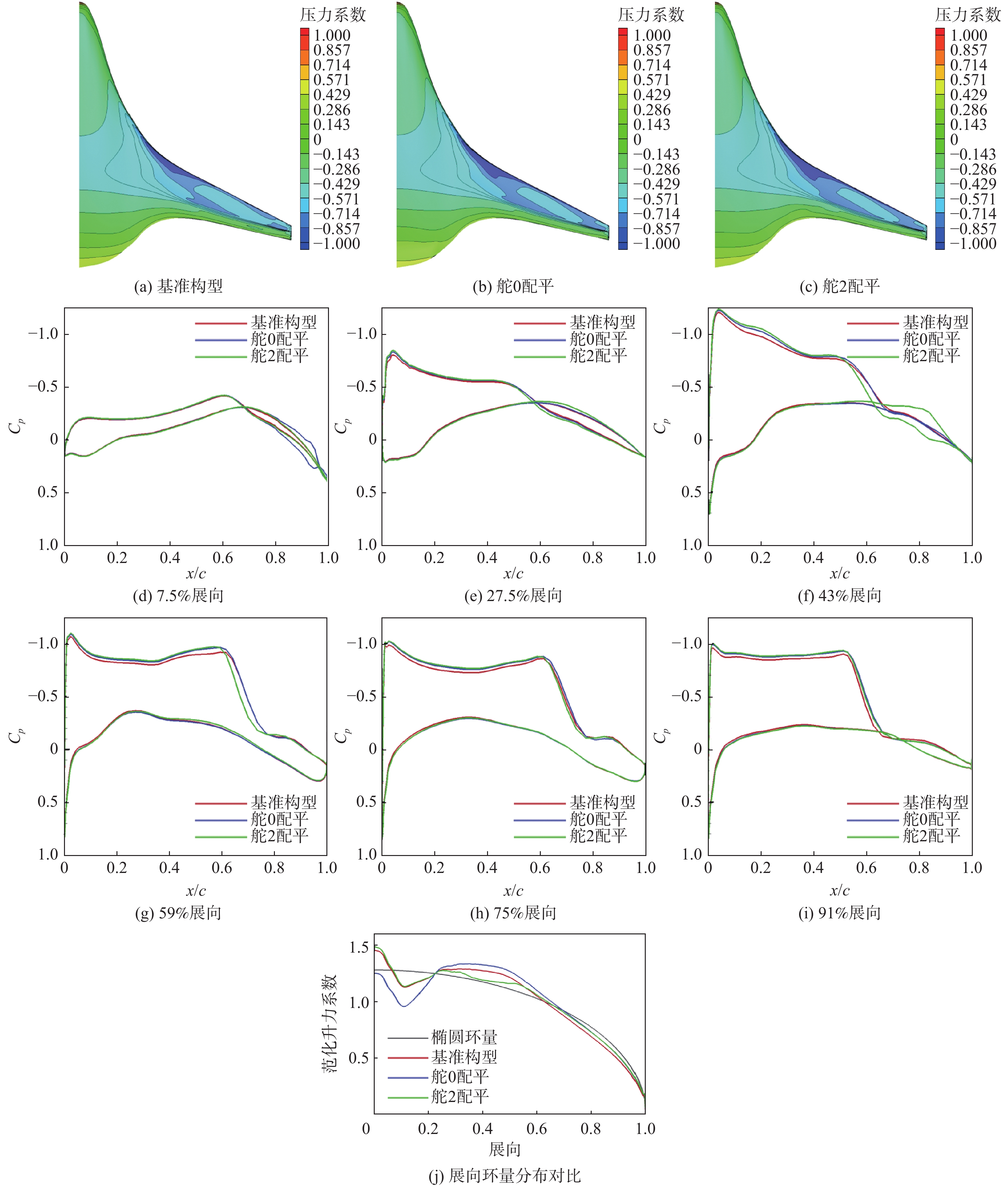
图 14 ${C_L} = 0.24$时不考虑俯仰配平时变弯度前后对比
Figure 14. Comparison of baseline configuration and variable camber configuration without considering pitch trim (${C_L} = 0.24$)
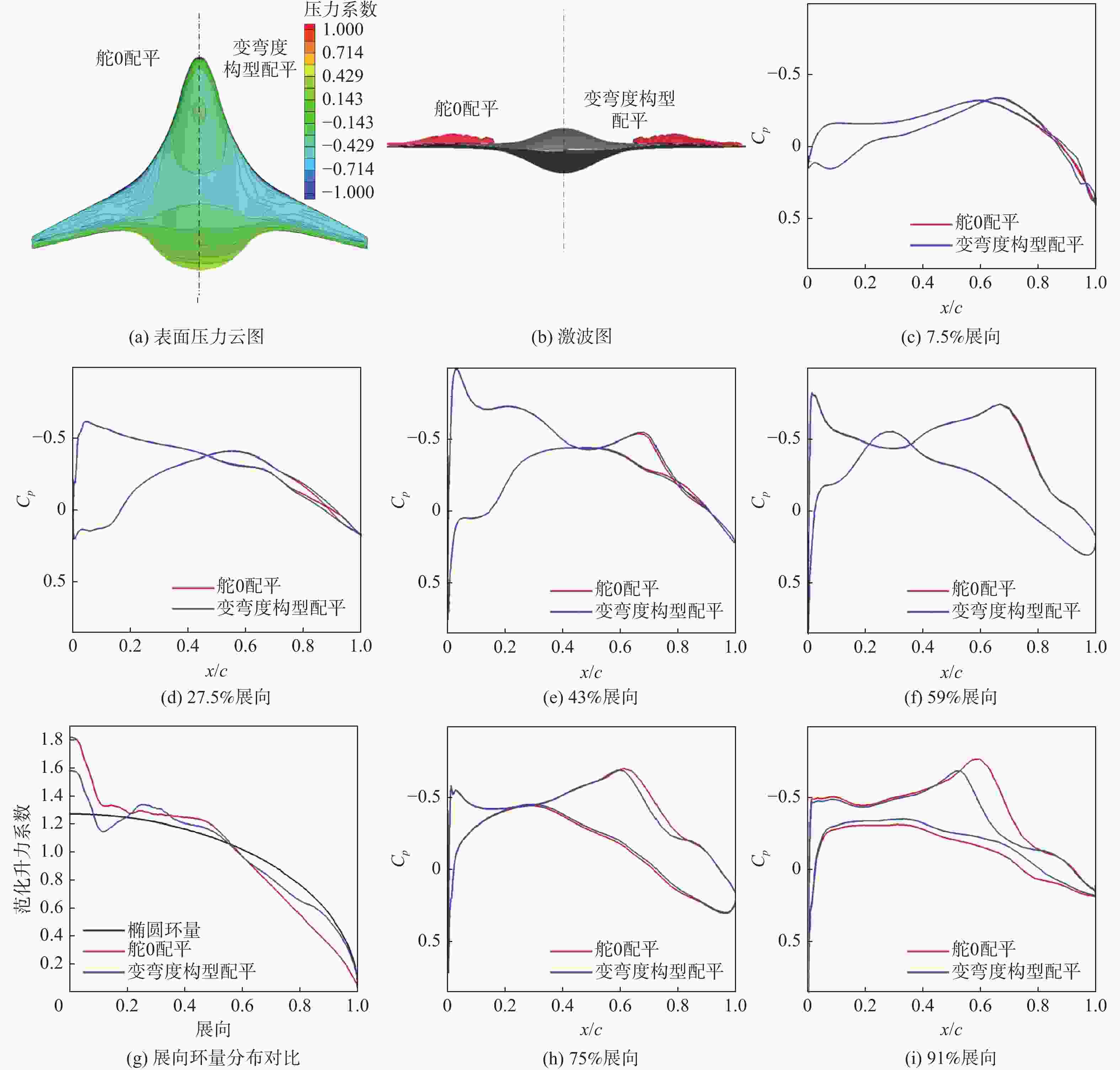
图 15 ${C_L} = 0.14$时中央体后缘配平与变弯度配平对比
Figure 15. Comparison of central body trailing edge trim configuration and variable camber trim configuration (${C_L} = 0.14$)
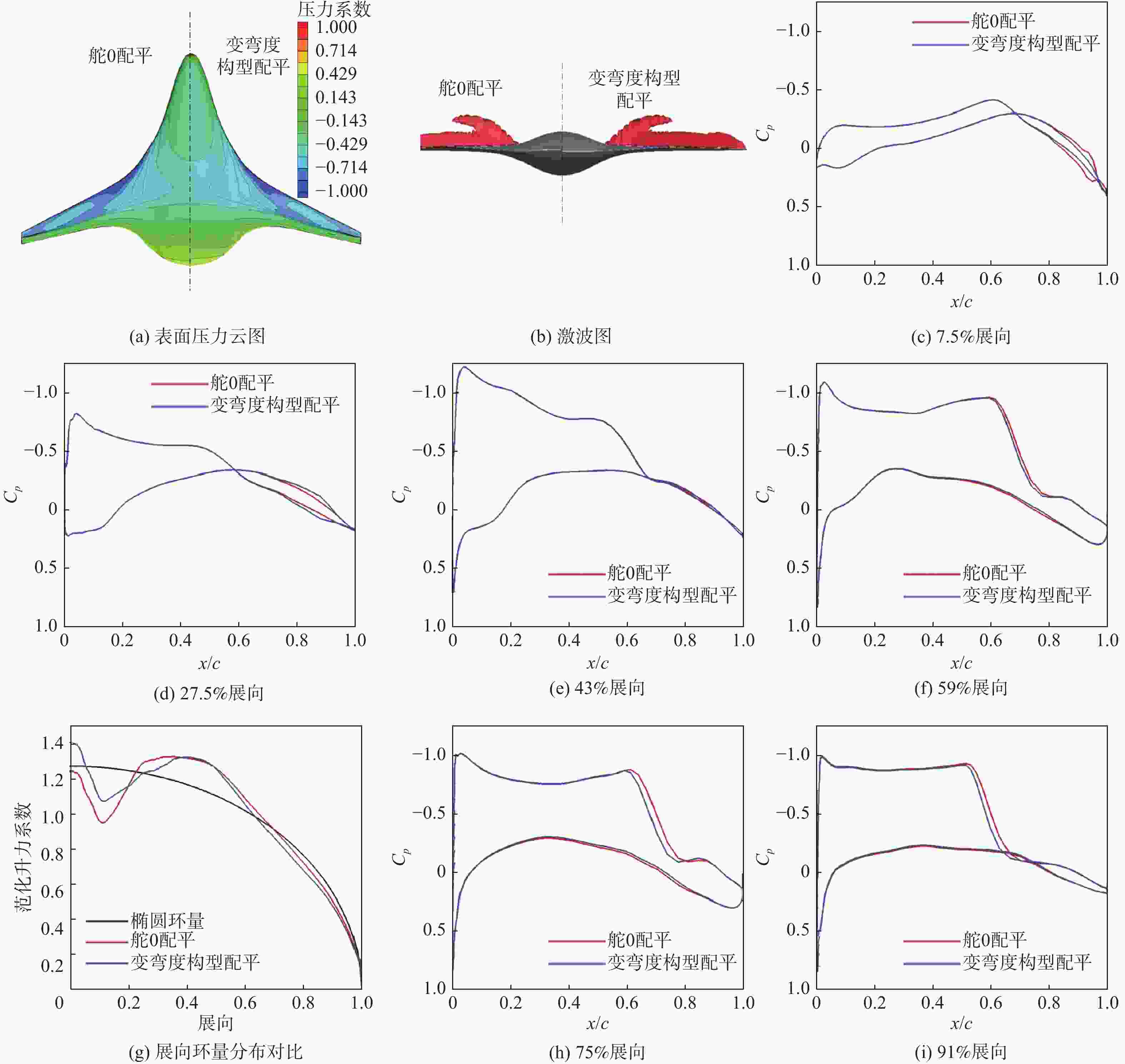
图 16 ${C_L} = 0.24$时中央体后缘配平与变弯度配平对比
Figure 16. Comparison of central body trailing edge trim configuration and variable camber trim configuration (${C_L} = 0.24$)
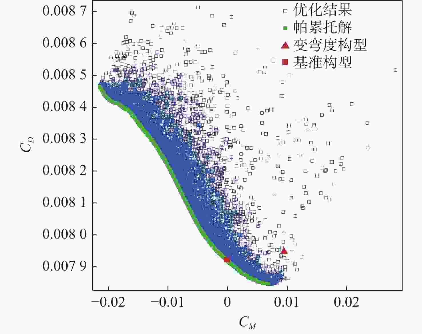
图 17 ${C_L} = 0.14$多目标优化pareto前沿
Figure 17. Multi-objective optimization pareto frontier (${C_L} = 0.14$)

图 18 ${C_L} = 0.24$多目标优化pareto前沿
Figure 18. Multi-objective optimization pareto frontier (${C_L} = 0.24$)

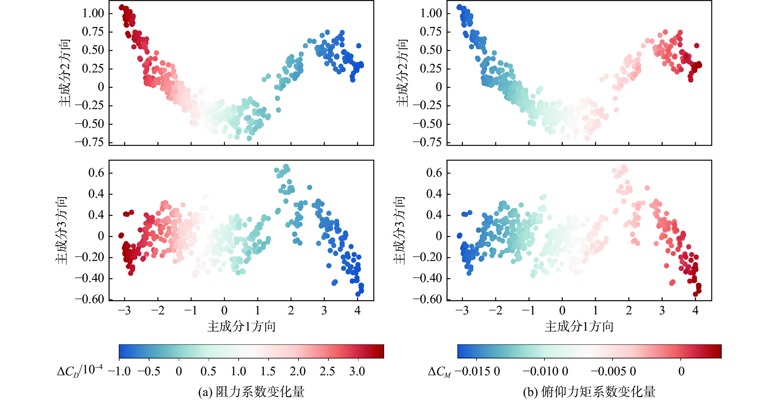
图 19 ${C_L} = 0.14$时PCA降维后不同组合舵偏下气动阻力及俯仰力矩系数变化云图
Figure 19. Contour of aerodynamic drag and pitch moment coefficients under different combinations of flap deflection after PCA dimension reduction (${C_L} = 0.14$)
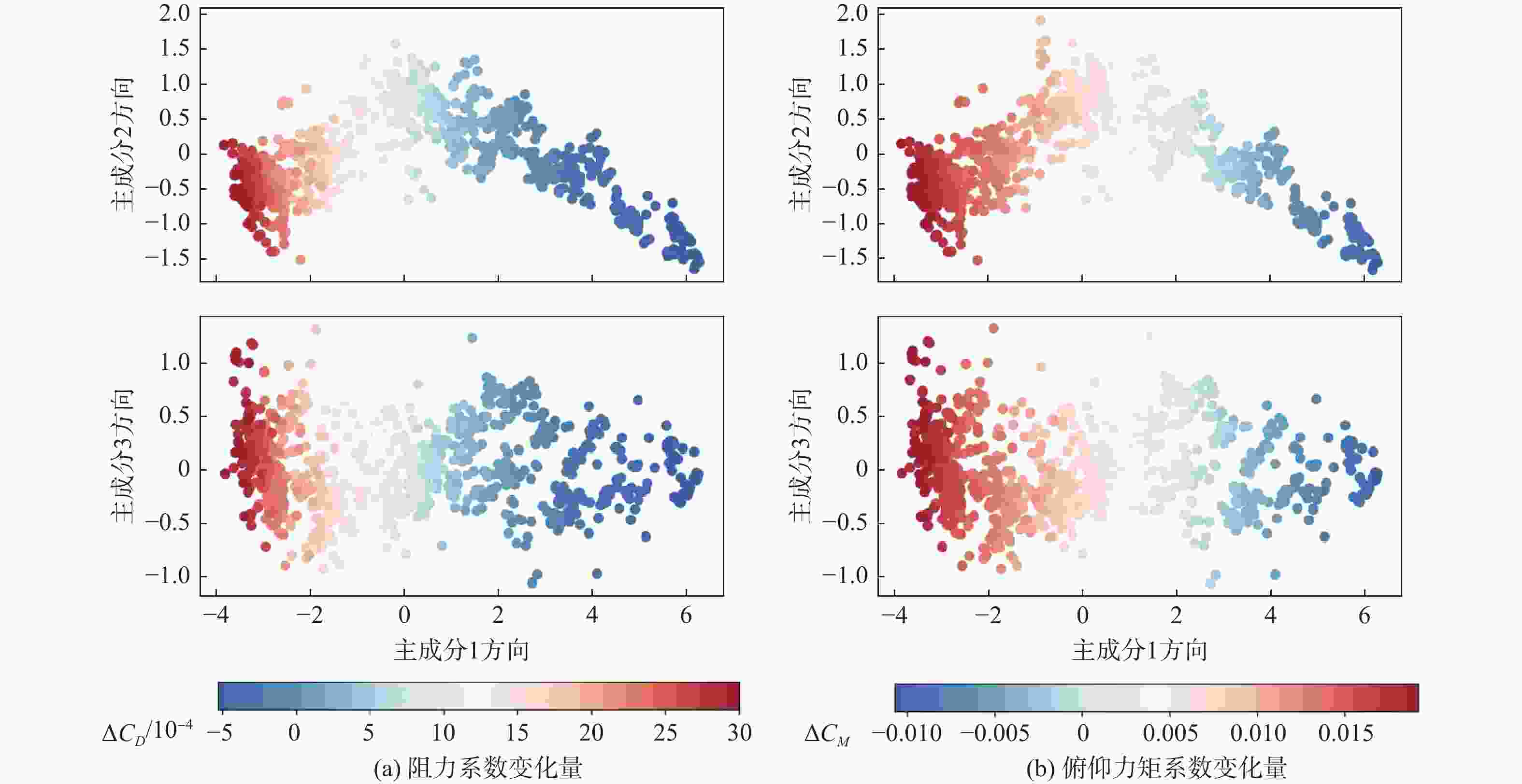
图 20 ${C_L} = 0.24$时PCA降维后不同组合舵偏下气动阻力及俯仰力矩系数变化云图
Figure 20. Contour of aerodynamic drag and pitch moment coefficients under different combinations of flap deflection after PCA dimension reduction (${C_L} = 0.24$)
表 1 基准构型气动力系数
Table 1. Aerodynamic coefficient of baseline configuration
α/(°) ${C_L}$ ${C_D}$ ${C_M}$ L/D 2.58 0.14 0.00795 0.0040 17.62 3.12 0.19 0.00904 0.0001 21.00 3.63 0.24 0.01148 −0.0049 20.91  下载: 导出CSV
表 2 ${C_L} = 0.14$时基准构型与单舵面配平构型气动力系数
Table 2. Aerodynamic coefficient of baseline configuration and single flap trim configuration (${C_L} = 0.14$)
布局 舵 0/(°) 舵 1/(°) 舵 2/(°) 舵 3/(°) 舵 4/(°) 舵 5/(°) α/(°) ${C_D}$ ${C_M}$ $\Delta {C_D}$/10−4 基准构型 0 0 0 0 0 0 2.58 0.00795 0.0040 0 舵0 配平 4.91 0 0 0 0 0 2.41 0.00817 0.0003 2.2 舵5 配平 0 0 0 0 0 3.83 2.37 0.00806 0.0001 1.1
下载: 导出CSV
表 3 ${C_L} = 0.24$时基准构型与单舵面配平构型气动力系数
Table 3. Aerodynamic coefficient of baseline configuration and single flap trim configuration (${C_L} = 0.24$)
布局 舵 0/(°) 舵 1/(°) 舵 2/(°) 舵 3/(°) 舵 4/(°) 舵 5/(°) α/(°) ${C_D}$ ${C_M}$ $\Delta {C_D}$/10−4 基准构型 0 0 0 0 0 0 3.63 0.01148 −0.0049 0 舵0 配平 −5.89 0 0 0 0 0 3.82 0.01228 −0.0001 8 舵2 配平 0 0 −2.11 0 0 0 3.93 0.01211 −0.0001 6.3
下载: 导出CSV
表 4 设计点Kriging代理模型精度验证结果
Table 4. Results of validation for Kriging model under design point
气动性能 最大预测误差 平均预测误差 ${C_L}$ 6.3×10⁻⁴ 2.5×10⁻⁴ ${C_D}$ 1.2×10⁻⁴ 6.8×10⁻⁴ ${C_M}$ 7.6×10⁻⁴ 2.9×10⁻⁴
下载: 导出CSV
表 5 不考虑俯仰配平时变弯度减阻优化结果
Table 5. Results of variable camber drag reduction optimization without considering pitch trim
${C_L}$ 舵 0/(°) 舵 1/(°) 舵 2/(°) 舵 3/(°) 舵 4/(°) 舵 5/(°) α/(°) ${C_D}$ ${C_M}$ $\Delta {C_D}$/10−4 0.14 0 0 0 0 0 0 2.58 0.00795 0.0040 0 −0.21 0.02 −1.11 −1.28 1.31 0.09 2.80 0.00787 0.0072 −0.8 0.24 0 0 0 0 0 0 3.63 0.01148 −0.0049 0 1.46 2.65 0.09 0.74 0.89 2.25 3.22 0.01095 −0.0157 −5.3
下载: 导出CSV
表 6 考虑配平约束时变弯度减阻优化结果
Table 6. Results of variable camber drag reduction optimization when considering pitch trim
${C_L}$ 舵 0/(°) 舵 1/(°) 舵 2/(°) 舵 3/(°) 舵 4/(°) 舵 5/(°) α/(°) ${C_D}$ ${C_M}$ $\Delta {C_D}$/10−4 0.14 0 0 0 0 0 0 2.58 0.00795 0.0040 0 4.91 0 0 0 0 0 2.41 0.00817 0.0003 2.2 0.681 1.75 −0.501 −0.0914 0.422 1.65 2.45 0.00792 0.0004 −0.2 0.24 0 0 0 0 0 0 3.63 0.01148 −0.0048 0 −5.89 0 0 0 0 0 3.82 0.01228 −0.0001 8 −1.18 −2.47 0.496 −0.423 −0.528 −0.186 3.83 0.01199 −0.0003 5.1
下载: 导出CSV
表 7 ${C_L} = 0.14$时主成分元素对应情况
Table 7. Principal component elements correspondence (${C_L} = 0.14$)
主成分 舵 0/(°) 舵 1/(°) 舵 2/(°) 舵 3/(°) 舵 4/(°) 舵 5/(°) 主成分1(93.73%) −0.426 −0.624 −0.172 −0.440 0.052 −0.451 主成分2(4.25%) 0.679 −0.524 −0.067 0.112 0.494 0.057 主成分3(1.05%) −0.199 −0.399 0.556 −0.161 −0.115 0.673 主成分4(0.41%) −0.090 −0.267 −0.729 0.276 −0.370 0.420 主成分5(0.32%) −0.101 0.323 −0.353 −0.574 0.517 0.405
下载: 导出CSV
表 8 ${C_{{L}}} = 0.24$时主成分元素对应情况
Table 8. Principal component elements correspondence (${C_{{L}}} = 0.14$)
主成分 舵 0/(°) 舵 1/(°) 舵 2/(°) 舵 3/(°) 舵 4/(°) 舵 5/(°) 主成分1(93.73%) −0.426 −0.624 −0.172 −0.440 0.052 −0.451 主成分2(4.25%) 0.679 −0.524 −0.067 0.112 0.494 0.057 主成分3(1.05%) −0.199 −0.399 0.556 −0.161 −0.115 0.673 主成分4(0.41%) −0.090 −0.267 −0.729 0.276 −0.370 0.420 主成分5(0.32%) −0.101 0.323 −0.353 −0.574 0.517 0.405
下载: 导出CSV
-
[1] DEL ROSARIO R, FOLLEN G, WAHLS R, et al. Subsonic fixed wing project overview of technical challenges for energy efficient, environmentally compatible subsonic transport aircraft[C]//Proceedings of the 50th AIAA Aerospace Sciences Meeting including the New Horizons Forum and Aerospace Exposition. Reston: AIAA, 2012: 9-12. [2] LYU Z, MARTINS J R R A. Aerodynamic design optimization studies of a blended-wing-body aircraft[J]. Journal of Aircraft, 2014, 51(5): 1604-1617. doi: 10.2514/1.C032491 [3] REIST T A, ZINGG D W. Aerodynamic shape optimization of a blended-wing-body regional transport for a short range mission[C]//Proceedings of the 31st AIAA Applied Aerodynamics Conference. Reston: AIAA, 2013: 2414. [4] BROWN M, VOS R. Conceptual design and evaluation of blended-wing body aircraft[C]//Proceedings of the AIAA Aerospace Sciences Meeting. Reston: AIAA , 2018: 0522. [5] 王刚, 张彬乾, 张明辉, 等. 翼身融合民机总体气动技术研究进展与展望[J]. 航空学报, 2019, 40(9): 7-35.WANG G, ZHANG B Q, ZHANG M H, et al. Research progress and prospect for conceptual and aerodynamic technology of blended-wing-body civil aircraft[J]. Acta Aeronautica et Astronautica Sinica, 2019, 40(9): 7-35 (in Chinese). [6] OKONKWO P, SMITH H. Review of evolving trends in blended wing body aircraft design[J]. Progress in Aerospace Sciences, 2016, 82(1): 1-23. doi: 10.1016/j.paerosci.2015.12.002 [7] MARQUES M, GAMBOA P, ANDRADE E. Design of a variable camber flap for minimum drag and improved energy efficiency[C]//Proceedings of the 50th AIAA/ASME/ASCE/AHS/ASC Structures, Structural Dynamics, and Materials Conference. Reston: AIAA, 2009: 2196. [8] MARTINS J R R A. Fuel burn reduction through wing morphing[J]. Green Aviation, 2016, 9(8): 73. [9] KAUL U K, NGUYEN N T. Drag optimization study of variable camber continuous trailing edge flap (VCCTEF) using OVERFLOW[C]//Proceedings of the 32nd AIAA applied aerodynamics conference. Reston: AIAA, 2014: 2444. [10] URNES J, NGUYEN N. A mission adaptive variable camber flap control system to optimize high lift and cruise lift to drag ratios of future n+3 transport aircraft[C]//Proceedings of the 51th AIAA Aerospace Sciences Meeting including the New Horizons Forum and Aerospace Exposition. Reston: AIAA, 2013: 214. [11] TING E, DAO T, NGUYEN N T. Aerodynamic load analysis of a variable camber continuous trailing edge flap system on a flexible wing aircraft[C]//Proceedings of the 56th AIAA/ASCE/AHS/ASC Structures, Structural Dynamics, and Materials Conference. Reston: AIAA, 2015: 1839. [12] IPPOLITO C A, NGUYEN N T, TOTAH J, et al. Initial assessment of a variable-camber continuous trailing-edge flap system for drag-reduction of non-flexible aircraft in steady-state cruise condition[C]//Proceedings of the AIAA Infotech@Aerospace Conference 2013. Reston: AIAA, 2013: 5143. [13] NGUYEN N T, XIONG J, SAGER J. Fuel-optimal trajectory optimization of mach 0.745 transonic truss-braced wing with variable camber continuous trailing edge flap[C]//Proceedings of the AIAA Aviation 2021 Forum. Reston: AIAA, 2021: 2575. [14] XIONG J, BARTELS R E, NGUYEN N T. Aeroelastic trim drag optimization of mach 0.745 transonic truss-braced wing aircraft with variable-camber continuous trailing-edge flap[C]//Proceedings of the AIAA Aviation 2021 Forum. Reston: AIAA, 2021: 2528. [15] NORRIS G. Boeing unveils plans for trailing edge variable camber on 787 to reduce drag, save weight[EB/OL]. (2006-06-12)[2006-06-12]. http://Tlightglobal.com/news/articles.2006. [16] THOMAS A R, KOO D, ZINGG D W. Aircraft cruise drag reduction through variable camber using existing control surfaces[J]. Journal of Aircraft, 2022: 1-10. [17] 何萌, 杨体浩, 白俊强, 等. 基于后缘襟翼偏转的大型客机变弯度技术减阻收益[J]. 航空学报, 2020, 41(7): 165-180.HE M, YANG T H, BAI J Q, et al. Drag reduction benefits of variable camber technology of airliner based on trailing-edge flap deflection[J]. Acta Aeronautica et Astronautica Sinica, 2020, 41(7): 165-180(in Chinese). [18] MITRIDIS D, PAPANIKOLATOS N, PANAGIOTOU P, et al. Morphing technologies assessment on a tactical BWB UAV reference platform[C]//Proceedings of the AIAA Scitech 2022 Forum. Reston: AIAA, 2022: 1985. [19] DEB K, AGRAWAL S, PRATAP A, et al. A fast elitist non-dominated sorting genetic algorithm for multi-objective optimization: NSGA-Ⅱ[C]//Proceedings of the International conference on parallel problem solving from nature PPSN VI: 6th International Conference. Berlin : Springer, 2000: 849-858. [20] 李莉. 基于遗传算法的多目标寻优策略的应用研究[D]. 无锡: 江南大学, 2008.LI L. Application research on multi-objectives optimization based on the genetic algorithm[D]. Wuxi: Jiangnan University , 2008. [21] LIOU M F, KIM H, LEE B, et al. Aerodynamic design of integrated propulsion–airframe configuration of a hybrid wing body aircraft[J]. Shock Waves, 2019, 29(8): 1043-1064. doi: 10.1007/s00193-019-00933-z [22] FELDER J, KIM H, BROWN G, et al. An examination of the effect of boundary layer ingestion on turboelectric distributed propulsion systems[C]//Proceedings of the 49th AIAA Aerospace Sciences Meeting including the New Horizons Forum and Aerospace Exposition. Reston: AIAA, 2011: 300. [23] CAI Y, XIE J, HARRISON E, et al. Assessment of longitudinal stability-and-control characteristics of hybrid wing body aircraft in conceptual design[C]//Proceedings of the AIAA AVIATION 2021 FORUM. Reston: AIAA, 2021: 2448. [24] ABDI H, WILLIAMS L J. Principal component analysis[J]. Wiley Interdisciplinary Reviews: Computational Statistics, 2010, 2(4): 433-459. doi: 10.1002/wics.101 [25] CARREIRA-PERPINAN M A. Continuous latent variable models for dimensionality reduction and sequential data reconstruction[D]. Sheffield : University of Sheffield, 2001. -

 下载:
下载:


 点击查看大图

计量
- 文章访问数: 208
- HTML全文浏览量: 106
- PDF下载量: 21
- 被引次数: 0
